Working together the vacuum pumps, manifold, and bombarder form the basic requirements for processing neon lighting. The pumps and manifold allow units to be cleaned (heating) and then emptied of impurities (evacuation), before a small quantity of one or more rare gasses is added at a controlled pressure (filling).
The bombarder comprises all the electrical equipment needed to provide the high voltage, high current power required for the heating and cleaning process inside the unit.
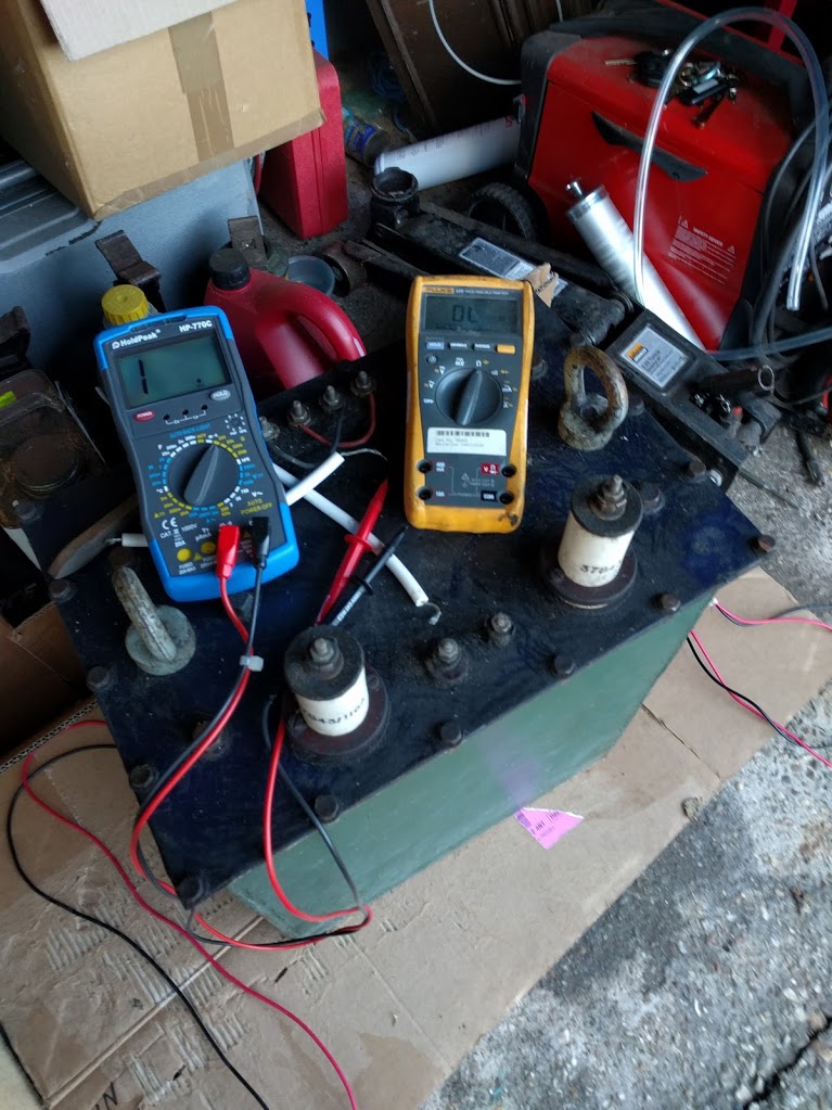
The high voltage transformer used for bombarding needs to meet a few requirements to be capable of handling a wide range of jobs. The key properties are normally the maximum apparent power rating, given in volt-amps (VA) or kilovolt-amps (KVA), and the open circuit voltage of the high voltage side of the transformer.
The power rating determines the maximum current for a given voltage level (as 
On the other hand, the range of high voltage outputs offered by the transformer will decide the lengths of tubing it is capable of dealing with: longer units require a higher potential difference (voltage) in order to break down the greater volume of gas present in the tube. Some transformers have a fixed, single high voltage output while others use a combination of primary windings to allow one of two or more output voltage levels to be chosen.
Most simple transformers that can be re-purposed for neon bombarding (including “pole pig” distribution transformers and utility potential transformers) have a single winding for both the primary and secondary and so have a fixed ratio and output voltage for any given input voltage.
A good compromise if you can’t find anything else, and don’t feel like importing a whole oil-filled pole pig from the states is to use a second hand resin cast potential transformer from Europe or the US. These can be found for under £500 with primary windings suitable for 220/240V use. Expect shipping costs to be painful as they weigh around 30KG. Although they are often rated around 2KVA (for 24/7 continuous use) they are made for demanding grid applications: safety monitoring and powering remote metering and switching equipment and so have very generous tolerances. I’ve run them at up to 5KVA for similar periods of time to bombarding uses, and they barely warm up. That’s easily enough poke to process small units (up to a few meters even) and they are a fraction of the size and weight of an oil cooled model. I have a 2KVA 220/14400V PT here that I was planning to use for bombarding until I found my Masonlite.


With all that said, a purpose built bombarding transformer offers a number of benefits over scavenging equipment from the utilities: many offer two output voltages, often 10,000V and 20,000V, allowing a wider range of lengths to be processed. The hardware (including high and low voltage bushings, oil level check/fill, and mounting hardware) is often smaller and easier to work with for equal power ratings, and some models include a current transformer or other means for metering the secondary current.
I was lucky to find a second hand (actually more like tenth hand…) Masonlite 20KVA bombarding transformer for sale on eBay for a couple of hundred pounds. This was a great find – similar new models sell for more than ten times this price – and was the tipping point to really kick off the whole neon project.
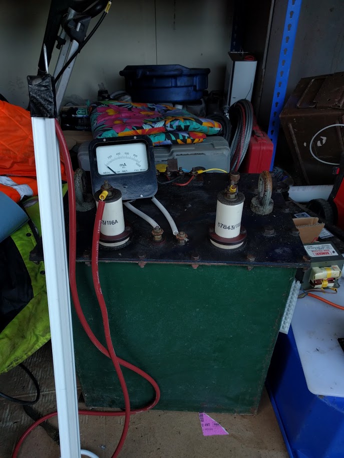
The transformer has a dual primary arrangement: the low voltage winding is split into two coils with independent terminals. This allows the windings to be run in either series (10,000V operation), or parallel (20,000V operation). The high voltage windings emerge from a pair of porcelain bushings on the top, and the oil fill / level port is accessible from the top. The transformer also has terminals to attach a bombarding milliammeter.
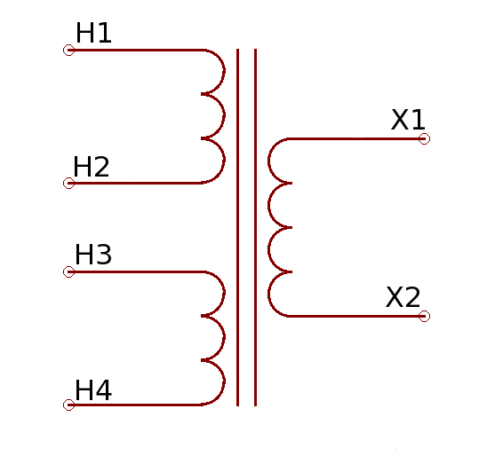
The schematic shows the logical arrangement: to run the primaries in series, power is applied between H1 and H4, and H2 and H3 are shorted together. To run in parallel, power is applied independently between H1-H2, and H3-H4. The high voltage output develops between X1 and X2.
This arrangement needs a series / parallel load switch in order to make it easy to switch between the ranges: since it needs to be able to carry up to 100A at mains voltage, it’s a pretty big switch.
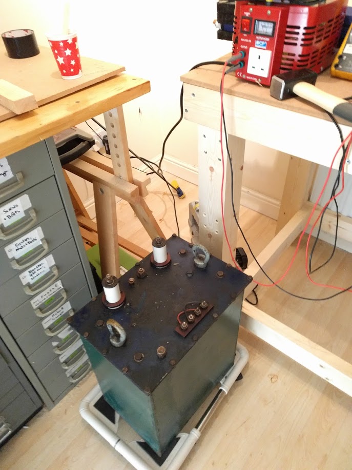
Because of its size and weight, the transformer was one of the first things to be installed (as soon as the benches were built). It sits on a little dolly so that it can be moved around if needed.

Any suggestion where in the UK (or Europe) to source a 2KVA 220/14400V PT or similar? (new or 2nd hand)
Thanks for fascinating blog!
LikeLike
Hi Brian, loved the blog mate 👍 I have a similar set up with the series/ parallel switch. The pump stand in question is an old masonlite, an early early version. The thing nearly went on fire 🔥, lol. The ancient cloth braid covered wire had given up the ghost, shorted out and attempted self termination. I have drawn on the depth of my knowledge and experience and rewired the burnt out wiring. the variable resistor, large and small contactors seem to be working fine. I do not know, and have used up all cognitive function for working out how to connect the secondary 240 from the contactor through the choke to the afore mentioned switch. The transformer terminals have been numbered 1-4 with what appears to be corresponding numbers on the switch. One direction operates a double connection and the other way a single. Any help here would be fantastic. 😁How the hell did I get in to this game?? 😂😂
LikeLike
If the transformer has four terminals it’s likely a split primary arrangement like mine (also a Masonlite), so you can use the same kind of serial/parallel load switch shown in the articles. If you’re not sure how the switch is wired you can measure continuity at the output with nothing connected – in series there will be two connections shorted together, and in parallel two pairs of output each with one live and one neutral connection.
LikeLike