In the last post we looked at the steps to build a simple strain viewer, or polariscope. In this article we’ll try to improve on that design to produce a more robust, smaller, and more usable device.
The principals are exactly the same – the light source and two polarising filters to produce plane polarised light, and to filter out the light that passes directly through the sample. The only difference is that this time we’ll use a larger stage area, and a more sturdy case to house the unit.
Material concerns
Many of the parts from the original build are re-used here. The light source, diffuser layer, and analyser (second polariser) are recycled and most of the new components form parts of the housing and supports for the optics.
The main additions this time are:
- Wooden case (recycled from an electrostatic voltmeter that was DoA)
- 5mm polycarbonate sheet (Perspex® or Lexan®)
- Black photographic mounting card for light screening
- 4 x porcelain bushings to support the analyser
- 2 x 150mm x 150mm polarising film for stage
And the parts re-used from last time:
- 10W LED floodlight
- Parchment paper diffuser
- 72mm Hoya linear polarising filter
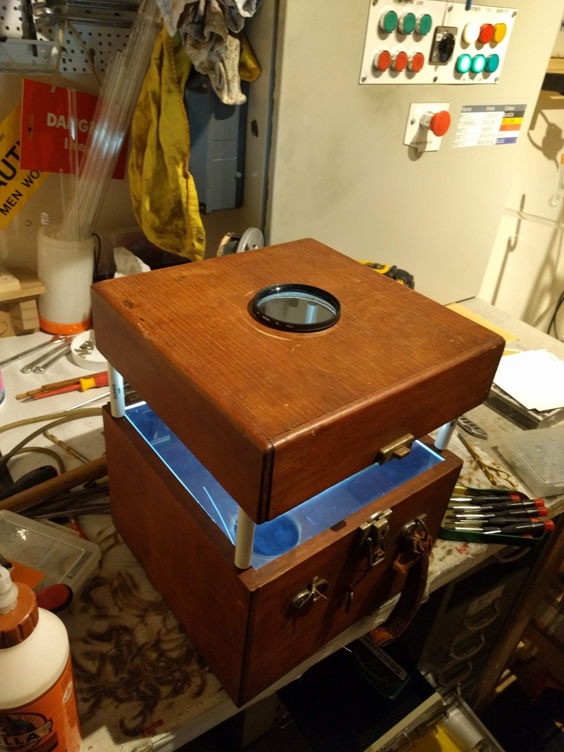
The basic scheme of the polariscope is the same as the original cardboard version: a light source in the box shines through a diffuser and first polariser, then through the sample and into the analysing polariser.

You can use any components that you have to hand that will allow this arrangement to be made – I had a nice looking wooden box lying around, as well as some old porcelain standoffs / bushings that seemed about the right size, but you could use an ABS plastic “project box” style enclosure, nylon standoffs, or whatever other materials you have access to that will produce a reasonably strong and robust case for the project.
The plastic polariser film is used in this build in place of the 72mm photographic filter. This is fairly cheap and easy to come across, although it does not provide as high a quality of polarised light: the filter has greater leakage of unpolarised light and this makes the dark field look more grey than the blue-black of a high quality glass filter. If the available light source is bright enough two layers of the film can be stacked together to improve the situation somewhat. The upside of this change is that the stage area is more than four times larger – allowing more detail to be observed at one time without needing to move the object around.
Building big
With the parts I had selected, the first step is to mark up and cut a piece of polycarbonate to fit the existing recess in the wooden case. If you don’t have a recess in the box you plan to use, you can either make one, or use screws, glue or another means of fixing the sheet down. As long as you can access the switch for whatever light source you use there’s no need to access the interior once the device has been built unless you need to replace something.
If you’re using plastic sheet for the stage the easiest way to cut it is with a plastic knife: a bit like using a glass cutter to mark and cut sheet glass, you first make a deep scratch in the plastic surface and then snap it over a straight edge to make the cut.
Since the area of the stage is limited by the size of the polarising film (mine is 150mm square), I also needed to create a border to block out excess light from reaching the stage and analyser. It’s still possible to view strain in a sample without doing this but it makes for a better image and less eye strain if you block out the excess light from the lamp. I used heavy photographic mounting paper for this – it completely blocks the light, and is easy to cut with a scalpel or sharp knife.

As well as the border for the stage I cut a matching sized piece of parchment paper to act as the diffuser, and these layers were fixed to the underside of the stage using sticky tape.


At this point the light source and stage can be installed into the housing and tested to make sure that everything looks good. So long as you get a reasonably uniform illumination over the open area of the stage everything should work fine.
For the case that I was using at this point it was necessary to make some modifications to allow the lid to stand a little higher to create the space for the specimen to sit in. The box that I had is quite old and a little fragile so I also took the opportunity to add some strength to the enclosure with a couple of pins and some wood glue where the original joints had begun to come apart.

To secure the posts that support the lid and analyser I drilled out matching 7mm holes near to each corner (and avoiding existing nails and screws!). To add some more rigidity I then put small tinned copper inserts into each hole – these were made by cutting off the tails of some crimp style ring terminals that matched both the hole size and the threads on the standoffs that I had. One upside of these being copper is that they are fairly soft and you can make a good push fit with the standoffs (threaded inserts would have been better, of course, but for the life of me I couldn’t find anything to match the threads on the porcelain bushings I had, and after all this is neon shop class, not carpentry!).


With the inserts for the standoffs made the physical construction is almost complete. All that’s needed now is to find the centre of the lid and cut a hole for the analyser, and to mount the polarising film on top of the stage.
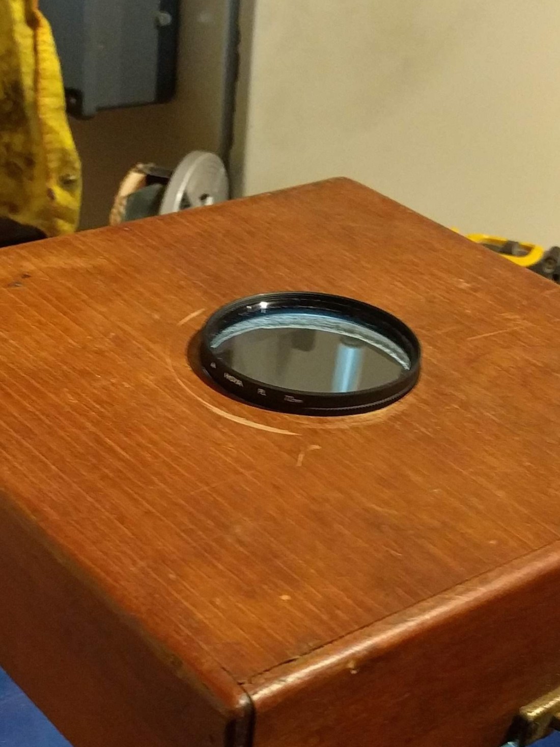
To make the hole I used a regular 74mm hole saw – this allows the filter to sit on the unit securely without risking slipping through. A couple of small blobs of hotglue fix it into place. It’s worth getting hold of a matching lens cap for the analyser since it will attract a lot of dust when not in use (canned air and lens paper or cloth are good for cleaning up).
Everything is ready for the final assembly now. The lid slips into place on the standoffs, and two sheets of 150mm square polarising film are placed on the stage. Ideally these would be mounted on the underside for better protection but I found that with the polycarbonate I had there was some distortion and fuzziness – presumably due to strain remaining in the material. A better option for a future update might be to use glass for the stage instead (or better quality sheet plastic!).


Although it’s still clunky compared to commercial models (and probably isn’t going to be the last polariscope I ever build) this is a big improvement on the cardboard prototype and is more practical for quickly examining and photographing a series of glass samples. If anything, with the standoffs the box is a little high – it’s easier to view on a fairly low bench without straining your neck to get a decent view.
Hopefully there’s some useful information here for anyone wanting to put together a quick and dirty polariscope for neon use. Join us in the next instalment for a quick guide to viewing strain in neon work, and a brief introduction to annealing techniques that can help to reduce the residual strain in worked glass.
