Welcome back to another home-brew neon equipment post. This time we’ll take a look at techniques for visualising strain (or stress) in glass.
Stress develops in glass when it cools unevenly from a softened or molten state. This often happens when the glass is cooled or heated rapidly or when the glass itself is uneven (perhaps because the thickness of the heated glass is not uniform). Mechanical forces that exist between the different parts of the glass cannot be resolved since part of the glass has already cooled back to the solid state. These forces remain trapped in the fabric of the material and may cause unpredictable breakage at some future time.
Very rapid heating or cooling may cause glass to immediately shatter from the stress – especially if some pre-existing strain is present.

In this post we will look at the construction of a very simple optical tool for examining stress in glass that can be built cheaply and with simple parts and materials. The total cost is under £20, and a simple device can be built in just a few minutes.
An extreme example of strain is the Prince Rupert’s Drop – shown in the image at the top of the post – these are the earliest known example of toughened glass. The drop is a small bead of glass with a thin tail, prepared by dropping a blob of molten glass into cold water. The shock of the sudden cooling sets up extreme stresses in the glass which allow the head of the bead to withstand enormous force – the impact of a bullet even. If the tail of the drop is snapped or broken however, the entire drop explosively disintegrates as the strain force overcomes the strength of the thin tail (much as a surface scratch allows a tube to be cleanly snapped).
Strain is pretty much always a bad thing in neon work, although there are types of manufactured glass that use internal strain to provide improved material properties (toughened glass and shatter resistant windscreens for vehicles are two examples).
The optical polariscope
A polariscope is an optical instrument designed to allow the user to visualise distribution of stress in transparent materials. Different types of polariscopes are used for different tasks, from tiny hand-held units for gemological analysis, up to very large table sized units and beyond for inspecting large pieces of laboratory glassware, windscreens, and other specialised glass, polymer and mineral applications.
Modern digital polariscopes also exist for ongoing monitoring of stress in a range of materials; these types of system go way beyond the scope of this discussion!
As the name suggests the tool relies on the special behaviour of polarised light as well as the property of photoelasticity displayed by some materials.
Polarised light is light in which the vibration or oscillation of the light wave is oriented along a particular direction (perpendicular to the axis of the beam). We describe the polarisation as the angle of orientation, for example, horizontal or vertical polarisation refers to two polarisation angles that are separated by 90º.
Normal light from the sun or a lamp is unpolarised: it consists of many different orientations of polarisation, with no distinct distribution as a result of the physical processes that produce the light. To make polarised light from unpolarised light, a polarising filter is used to reject all light waves not matching the specific polarisation state of the filter. A polarising filter is simply an optical filter that passes light of a certain polarisation while blocking light of all other polarisations. Polarising filters are made from engineered materials with specific optical properties, such as dichroism, Fresnel reflection, or birefringence.
A physical analogy can be found in a plucked string: if the string is plucked vertically, it can be said to be vertically polarised. On the other hand, if it is plucked crosswise it will vibrate side-to-side and has horizontal polarisation. A physical barrier that constrains the string’s motion is analogous to an optical polarising filter.
Technically, the type of polariscope we will put together here is known as a linear (or plane) transmission polariscope. Linear, since it relies on linear polarisation and transmission as the light used to view the specimen is transmitted through the material to reach the viewer.
Principle of operation
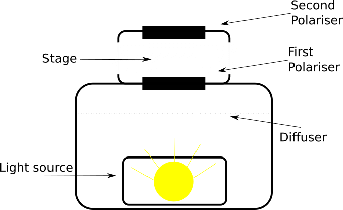
The polariscope consists of a light source and a pair of polarising filters mounted at 90º to one another (or in some cases, one filter rotates, and the operator must manually set the moving filter to the 90º alignment before use).
This arrangement causes the second filter (known as the analyser) to reject the polarised light from the first filter, causing the background viewed through the instrument to appear dark as most light reaching the analyser is of the wrong polarisation to pass through (this is sometimes known as a dark field arrangement, especially in microscopy).
The sample is placed between the two polarising filters and is observed through the aperture of the second filter.

In this way, light from the source passes through the first polariser and into the specimen. Depending on the material and strain present in the sample, the polarisation of the light from the polarising filter is changed as it passes through. Since this new polarisation no longer matches the rejection of the analyser, it will now pass through and be visible to the user. In this way the patterns of strain can be directly observed.
If the polariscope is equipped with additional filters or elements (quarter wave plates and a calibrated graticule or grid) it can be used to make measurements of various properties of the material and the strain within it. This is not necessary for typical strain checking in glass working but is often used in laboratory or industrial applications.
My very first polariscope was a cheap handheld gemological model from Amazon. It works, and is sort-of usable with glass, however the very small stage area (28mm is the outside diameter – the stage is a little shy of an inch) and awkward access for larger pieces of glass make it an impractical choice for this purpose.
Homebrew polariscope v1
Although they are potentially powerful and sophisticated instruments, a simple polariscope for viewing strain in glass, plastics, and mineral samples can easily be built for minimal cost. All that is required is a diffuse light source, a couple of polarising filters of appropriate size, and something to hold all the pieces together and shield excess light from the viewer.
Small polariscopes for gemological, laboratory, and glass use often consist of a light box containing a lamp and the first polariser, with a stage on top for the specimen to be placed on. A shelf or other support is then provided to position the analyser over the stage area, allowing the sample to be viewed from the top for inspection.
For the optics I used a cheap pair of Hoya and DynaSun® 72mm photographic linear polarising filters. Cost on Amazon UK is around £5-10 each. These fit a standard camera thread and include a smoothly rotating bezel to set the polarisation angle. The glass and polarising filter are reasonably good quality and produce a very effective dark field when set at 90º.
You can also use circular polarisers if available, but these are typically more expensive (since they have additional optics to work with the focusing system of modern digital cameras) and although they can be useful for scientific work I did not expect to have much real use for them.

The housing is made from a cardboard box (the box from a set of Bearmach Land Rover swivel housings turned out to be the perfect size…). About 400mm wide by 250mm deep and standing around 300mm tall. This provides a good space for the light to spread out and a reasonable area for the stage on top. More cardboard from the box (one of the flaps) is used to make a simple “bridge” in which to mount the analysing filter.


Everything is held together with sticky tape (as all good prototypes should be). To combat annoying light reflections within the stage area the inside of the bridge was coloured black with a Sharpie®. This greatly improves contrast over a light coloured material (black camera felt would be a better option for a more sophisticated build).

The light source for this attempt is a fairly bright Luceco® rechargeable 10W floodlight. This has a built in reflector which spreads the beam out well, but produces a rather intense light at the centre – especially without the polariser in place! To provide additional diffusion and make viewing the output more comfortable a layer of translucent paper (greaseproof cooking parchment) was taped into the box to provide additional diffusion and to create a soft and even light in the sample viewing area.
Reflections on v1
The first attempt worked well to demonstrate the basic ideas and to let me get some experience using a polariscope. That said, it does have a few significant drawbacks:
- For the small stage size the overall unit is huge. It’s clunky to store, a bit fragile, and overall quite cumbersome despite working adequately.
- Using 72mm filters for both polarisers means that the perspective given by the height of the stage diminishes the effective size of the stage – the illuminated area is a relatively small circle in the view of the analyser.
As a proof of concept it worked well, but as a practical instrument it has some real disadvantages.
In a couple of future posts we’ll look at both using the polariscope to determine levels of strain in bent glass and annealing techniques to reduce stress, as well as an improved “version two” that solves some of the limitations of the previous build. Thanks for reading!

2 thoughts on “Straining the point”