In the last post we looked at a range of manual techniques for cutting glass tubing. Most of these rely on creating a scratch in the glass surface which then allows controlled cracking and separation of the ends.
It’s always easy to apply these methods to straight, unbent tubing and for this type of job these techniques are all that is needed. Sometimes however, it may not be possible to break the tubing in the conventional manner, either because it is awkward or impossible to get good leverage on the tube to snap it, or because the length of glass to be removed is just too short to be snapped. Trimming electrode doublebacks, or to make welds for continuation tubing are common cases where a different approach might be required.
In this post we’ll look at the design and build of a simple hot wire tube cutter for the neon workshop using common off the shelf parts.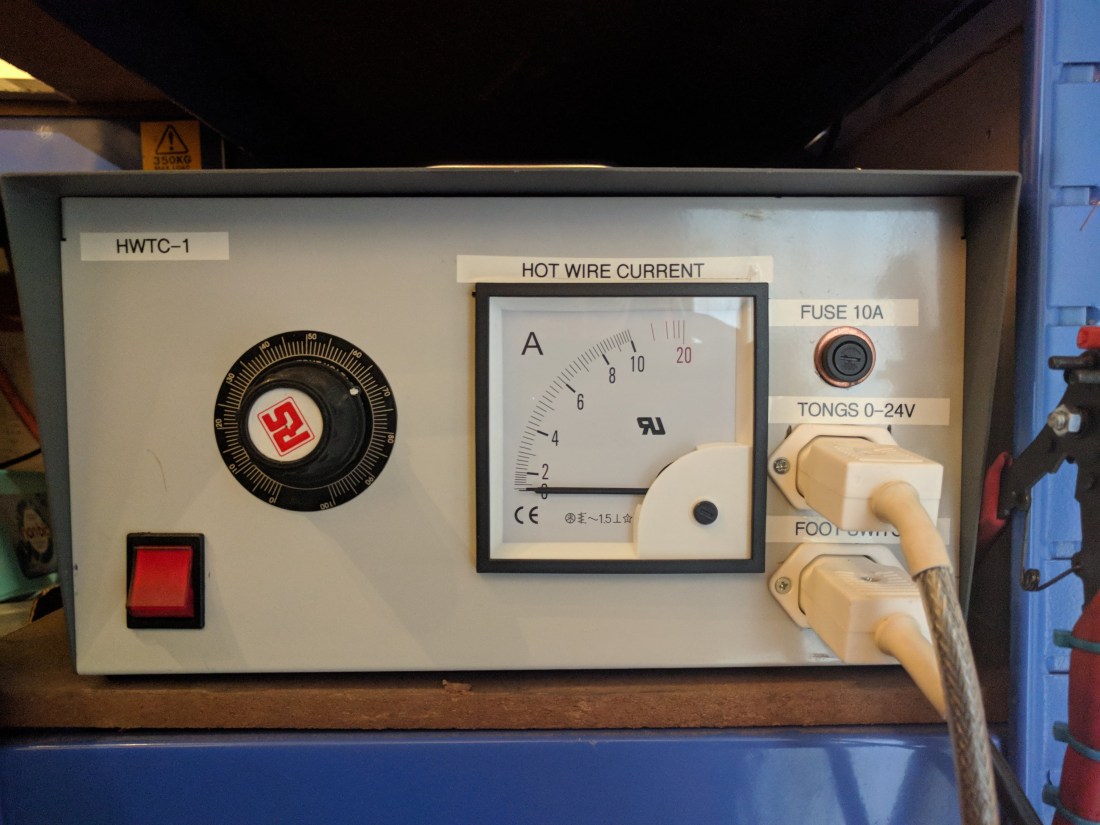
Hot wire cutters
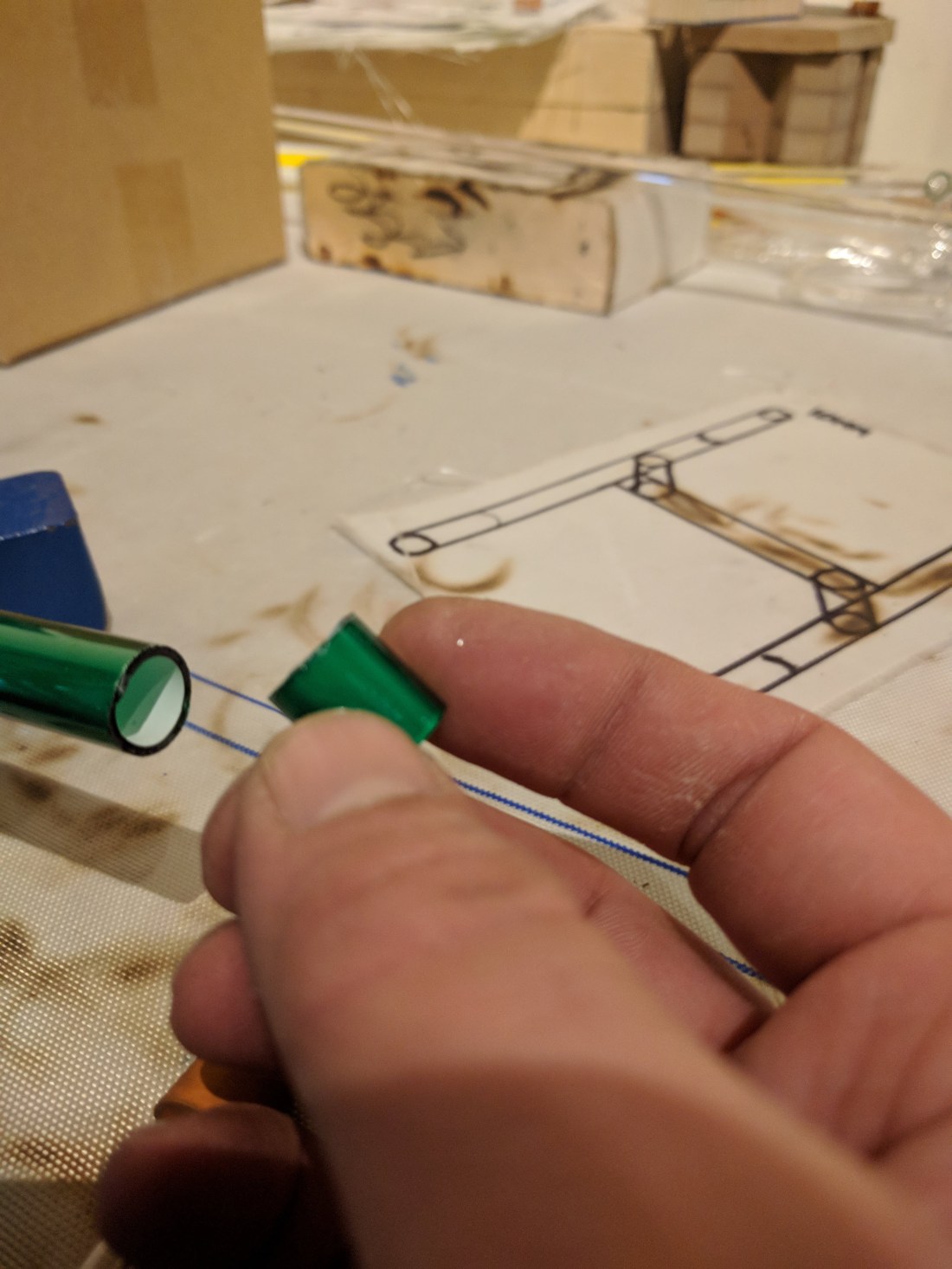
The basic idea of the hot wire tube cutter is to start a clean crack by subjecting a scratch in the glass surface to a sudden heat shock. This can be done using a piece of tubulation or glass rod that has been heated in the flame, but for making repeated cuts an electric cutter is quicker and more efficient.
The operating principle is simple: an electric current is passed through a length of resistance wire (nichrome or similar material), causing the wire to rapidly heat up to hundreds of degrees centigrade. When the wire is held against a piece of glass that has already been scratched, the rapid heating causes the glass to expand where it is in contact with the wire, forcing the edges of the scratch apart and initiating a crack.
For both safety and electrical reasons it’s best to use a relatively low voltage across the wire. This both reduces the risk of electric shock and provides maximum heating (since the power dissipated in the hot wire is proportional to the resistance and the square of the current – 
After receiving some eyebrow-raising quotes from commercial suppliers of hot wire cutting equipment I decided to build something myself.
Physically the cutter can be built in many different ways. The most common types for glass working use today have a bench mounted power supply, and either a hand, or foot switch to control the current. The resistance wire is a small loop, held between a pair of spring loaded tongs that tension the wire and keep it in place around the tubing to be cut.
Active resistance
The first step to design the tube cutter is to work out the rough electrical requirements. The cutter should run from a mains electrical supply (since it may consume up to a couple of hundred watts of power while in use), and this then needs to be stepped down to a manageable voltage that can be safely run to the tongs used to heat the glass. The design here is intended for 220-240VAC supplies but can easily be modified for 110-120VAC by changing the variac and transformer components.
I knew from models that I’d seen previously that these are typically rated around 200-300W. Assuming a maximum cutting voltage of 24V and working backwards this gives roughly 10A of current into a 2-3Ω load:


Which all seemed about in the right ball-park. This was then confirmed using a simple plug-in variable autotransformer (A Staco® in this case, but they’re just like a Variac™) to take measurements using various lengths and sizes of resistance wire. The voltage can be varied between around 0-30V and current measurements taken while observing the wire: when adequately heated it should glow a bright yellow-orange.

Testing confirmed the voltage and current ranges selected would be usable, and that the wire could be used to successfully crack a pre-scored piece of tubing.
Dramatic schematic
The circuit for the tube cutter is as simple as the rest of the project: a mains supply is routed via a fuse and switch to a variable transformer, and the variable transformer output feeds a low voltage step-down transformer. An additional fuse on the low voltage side provides added protection against a short circuit of the tongs.
The variable transformer allows the power output for a given length of resistance wire to be varied from 0..100% by reducing the output voltage. The “normal” setting is 50% which allows plenty of headroom if required. Since the power is dissipated in the wire, it will wear out faster when used with higher power: always try to use the lowest setting possible.
I decided to use a foot switch for this project, to allow both hands to be free to steady the glass and operate the cutting tongs.

The diagram shows a second switch in parallel with the foot switch: this was intended to be a panel switch allowing the cutter to be operated with either. In the end this was deleted from the design and replaced with a low-voltage fuse holder in the panel layout.
Parts department
With the electrical requirements sorted out it was time to start finding the remaining parts for the build. These are all pretty simple and straightforward, and many can be found cheaply from scrap or second hand. I decided to use all new, good spec components as I wanted a neat and tidy build that would fit into a particular gap in my existing benches.
The parts break down into hardware, cabling, electrical components, and connectors to link them all together. The case, switches, tongs and physical connections are really a matter of taste and can be changed to suit any specific needs.
The parts I used were mostly obtained from RS: items like the armoured cable for the footswitch and tongs, the tongs themselves, crimp connectors, heat shrink tubing, and bits of mounting hardware were scavenged from spares and scrap.
Links to the RS stock number for each item are given in brackets.
- Frame mount transformer, 200VA 2x24V o/p (503-938)
- 1Ph 1A Encapsulated Variable Transformer (890-2828)
- DPST on-off illuminated rocker switch (440-6890)
- Flange fixing fused IEC plug, 10A 250Vac (815-830)
- White flange fixing shuttered socket, 10A (x 2) (295-8709)
- IEC connector insulating boot,63.5×34.9×27.3mm (211-0907)
- Grey steel modular case, 300x200x160mm (232-819)
- Panel mount fuse holder; 250V (849-5670)
- AC Ammeter 96×96 90 deg 0-10/20A (901-0356)
- White re-wireable IEC straight plug,10A 250Vac (x 2) (295-8591)
- IEC connector insulated boot, 59×33.5×29.8mm (x 2) (801-932)

Total cost was around £275 although the project could have been done for a much lower price using scrap and second hand parts. One difficulty is that the small variacs don’t turn up at good prices very often in the UK: it’s easy to find ones in the 4-10A range, but that can make for a heavy and bulky build. It still beats Eberbach, who want eighteen hundred and fifty bucks for their fancy contraption!
Wire in a fire
Different models of tube cutter come with different arrangements for securing the resistance wire and to allow it to be held against the glass. The simplest is a pair of posts mounted on a desktop unit, with the wire held slackly between them. The glass is pressed down onto the wire between the posts and the current applied.
Many commercial cutters today come with a pair of tongs or pliers (side note: I don’t actually know what these things are called, but my first attempt was a pair of barbecue tongs, and the name has stuck). These serve to both hold the resistance wire, and to apply a spring loaded tension to it to help secure it around the glass. Often the resistance wire is formed into a small loop which will expand as the tongs are squeezed, and contract when they are released.
The barbecue tongs were a start, but they are quite sloppy and the spring force is weak. Also, being metal, they are prone to shorting out if they come into contact with the cutting wire.


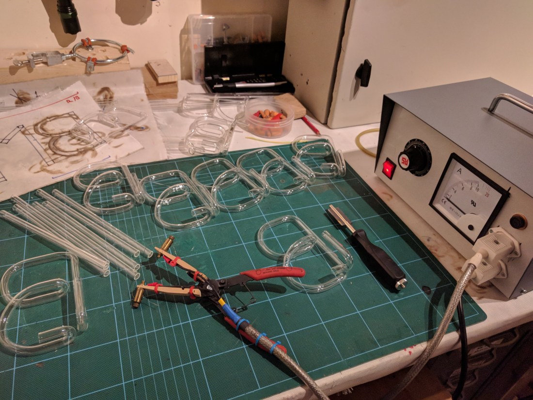
My second generation tongs were made from a pair of old circlip pliers (the type with the interchangeable jaws – you know, the ones that aren’t actually very good circlip pliers…) and a clothes peg.
The circlip pliers provide a comfy grip and a good spring tension, and the pegs extend the jaws out a little further. I found the spring slots in the pegs matched the prongs for the jaws on the pliers, so with a small woodscrew and a couple of cable ties they were securely held in place. The wire is fastened between a pair of old brass binding posts: this arrangement allows the resistance wire to be quickly and easily replaced if it snaps or burns out (you can keep a spare length on one side, and then just slacken off, pull through and re-tighten).
If you build it…
The physical build is straightforward: the most tricky part is cutting the necessary mounting holes for the plug, sockets, switches, and panel meter. This can be done in various ways depending on equipment available and time. A hydraulic press and a die cutter gives a very neat finish but costs a small fortune. Alternatives include drilling and sawing, using a “nibbler“, or simply attacking the panels with an angle grinder, cutting disk, and a steady hand. I went with the last option.


The cutting is simplified by creating a template for all the panel mounted hardware and sticking this to the panels prior to marking and cutting. It also provides some protection for the paint when drilling or cutting the metal.
With the cutting out of the way it’s time to loosely put all the components in place and then start working out the lengths of wire needed for each internal connection. Connections inside the device are made using crimped ring or disconnect terminals depending on the type of connection to be made.


For each connection on the schematic a length of wire is drawn out and held up to the chassis to determine fit (allowing for necessary length to clear any obstacles in the case). The wire is then cut, crimped and fixed in place. It helps to be methodical when doing this to avoid missed connections: I started with the incoming supply, and followed this along the schematic to the various internal components and then on to the output sockets.
All metal components should be grounded: I used one of the transformer mounting bolts to create a common internal earth point.
Once the connections have been measured out the fixings on all components can be tightened up and all connections put in place (depending on the parts used it may be necessary to make some connections before installing a component – e.g. some of the screws on the back of my variac were not accessible once mounted in the panel). If you are using insulating boots or other covers on the internal parts don’t forget to install them before making the final connection!
Testing testing… 1, 2, 3
With everything put together it’s time to carry out some tests. The first is a simple continuity test: starting at the incoming supply, trace the live and neutral paths to ensure expected continuity exists. A tester with an audible beep is handy for this. Also verify that no unexpected connections exist, e.g. from the live terminals to earth or neutral.
If you are nervous or worried about powering up at mains voltage it’s simple to plug the cutter into another variac to allow some basic checks without risking any drama. Set the variac to around 20% (~48V) and adjust the expected voltage output accordingly: for 100% on the tube cutter dial this would be about 4.8V and for 50% 2.4V.
With or without the variac, turn the unit on and connect a multimeter set for AC volts and an appropriate range across the tongs. Do not connect any resistance wire at this point. When operating the switch the multimeter should give a voltage reading in the expected range and the panel ammeter should remain around zero (it might twitch slightly when the power goes on). If everything goes well it’s safe to connect some resistance wire and start trying the cutter out.

Choose you resistance
Picking the length and size of resistance wire could almost be a topic for a whole post in itself. I didn’t find any particularly good guidance on this, so I just played around with different lengths, gauges, and power settings until I found something that seemed to work.
To get started I bought an assortment pack of three sizes: 24, 26, and 28AWG. These are available at low cost from suppliers like Amazon. since they are used by “vapers” who make their own heating coils.
I’ve mostly found myself using the 26 gauge, and with a length of wire between the binding posts of around 4-6″. If you find you are burning the wire out all the time, it’s too short or too thin for the power setting. On the other hand, if it takes forever to heat up it needs to either be thicker, or shorter, or the power should be increased.
With my normal resistance wire I leave the power setting on 50%: this seems fairly reasonable and ends up dumping about 100W into the wire. The current on the panel gauge is around 5A.
Once you seem to have things set up right, it’s worth practising for a while with bits of scrap tubing – the cutter can make very clean and tidy ends, but like other methods for cutting tubing it does rely heavily on the operator’s skill.
To wrap up today’s post, here’s a quick video showing me trimming a unit for an electrode weld from the day I finished the build. There’s some, ahem, “room for improvement” in the technique shown here, but it does show off the basic use.
