Welcome back to part two of this series on control systems for neon workshops (and apologies for the slightly longer than planned hiatus over the winter break!).
In this post we’ll look at the details of putting a system together, and the parts and circuit elements involved.
After looking at the requirements and high-level design in Standing in the way of control, we have an idea of what we are trying to achieve and the requirements for the finished system: now it’s time to choose parts that meet those goals and figure out exactly how to hook them all up together.

Although much less costly than the burners and processing equipment, the control gear still represents a significant investment and many modern commercial bombarding systems include fully integrated controls and a degree of automation.
Although it’s not necessary for the small shop to have all these high-end features a clear and easy to use means of controlling the equipment is important in keeping distractions to a minimum and letting the operator focus on the task in hand.
We finished off in the last article by looking at the loads the controller handles and the three functions it provides: switching, monitoring, and protection.
This time we’ll look at circuits to implement each of these functions and the components that can be used to put together a working system.
- Switching and power
- Bombarder switching
- Non-latching high current switching for bombarder
- 10KV/20KV switch (series/parallel load switch)
- Bombarder lockout and footswitch
- 110VAC supply for US appliances
- Latching start/stop for auxiliary loads
- Emergency stop cut out switches
- Bombarder switching
- Metering and monitoring
- Mains, load, HT, and emergency stop indicators
- Ballast and load volt meters
- Bombarding circuit ammeter
- Protection
- Fuses for each load and meter circuit
As well as these active functions the control cabinet needs to terminate the incoming power supply, and all of the connections to the various loads, remote switches, and other devices. It’s also necessary to consider the physical layout of the elements inside the cabinet in order to produce a build that is reliable and that can be maintained and extended as needed.
At the start of the design it’s useful to lay out the rough organisation of the system, and to start thinking about how each element will be laid out and connected. A block diagram is one way to get a sense of this without cluttering the page with the full detail of every interconnect: only the major connections are shown and some elements (for example the emergency stop switching) can be reduced to a simple abstract representation: a single switch for example.
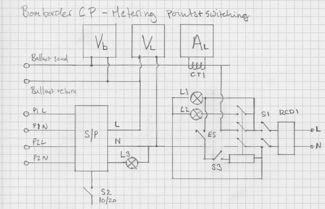 One of the first block diagrams to be prepared shows the metering and switching arrangements for the bombarding circuit: terminals for the ballast send and return, transformer supply, and incoming power are shown, as well as an outline of the indicators and metering points.
As the design progresses and more parts are defined or refined further block diagrams and outline schematics are prepared focusing on different areas or details of the system.
Bombarder switching
The bombarder is the main load in the neon shop and a substantial portion of the control gear is dedicated to switching and controlling the bombarding circuit.

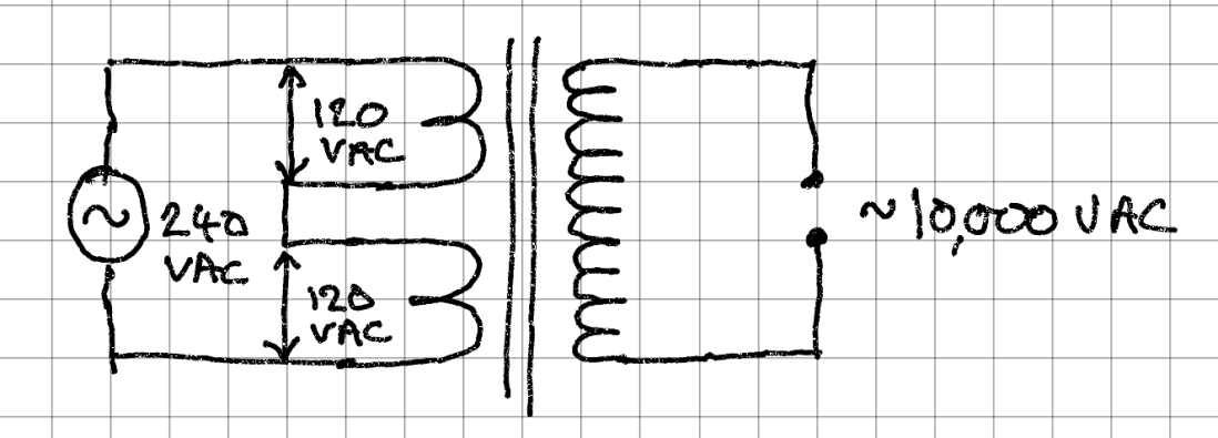
The bombarding transformer used is an oil-filled Masonlite 20KVA model with dual primary windings allowing the high voltage side to be run at either 10KV (primaries in series), or 20KV (primaries in parallel).

The primary windings are connected in series by linking X2 to X3 and applying power across X1 and X4. When used in parallel the full AC supply voltage is applied directly across both windings.

It should be possible to change the voltage selection on the transformer without having to change any cabling: the simplest way to implement a series/parallel load switch is to use a DPDT (double-pole/double-throw or double throw changeover) switch.
One terminal of each load is connected to one side of the supply and the switch is wired to both the supply and the remaining load terminals.
When in series configuration, the switch bridges the connection between the two loads allowing current to flow from the source in series. In this state the voltage is divided between the loads according to the ratio of their impedances.
In the opposite, parallel, configuration the switch supplies either power or a path to ground to each load this time completing the parallel circuit and applying the full supply voltage to both loads.

Manual switches of this type are available that can carry the kinds of currents required by the bombarding switch but they are large and cumbersome, and heavy to operate. To allow the voltage setting to be changed by a simple rotary or toggle switch a contactor is needed to switch the load separately from the control panel switch. Large contactors for switching inductive loads are not widely available with double-throw or changeover contact configurations: for this reason it is necessary to have separate contactors for the series and parallel sides of the circuit that are energised alternately to select one or other configuration.
Since the contactors work as a pair, and since a short-circuit would appear across the supply if both were energised simultaneously, it is important that they are interlocked electrically or mechanically to ensure that this cannot occur. In this case this is achieved simply by using a “centre-off” rotary cam switch that disconnects both circuits for a sufficient time for the contactor mechanism to release before allowing either to be reconnected.

I had a pair of 3-pole, normally open, 100A AC3 contactors in the workshop which made an ideal matched pair for the series/parallel switch. They are ABB AF52-30 22kW models rated AC1. This is acceptable since the S/P switch is never expected to interrupt the circuit under load. To adapt the DPDT circuit to a pair of contactors with all NO contacts it’s only necessary to separate out the two poles of the original to the two separate contactors and adapt the wiring accordingly.
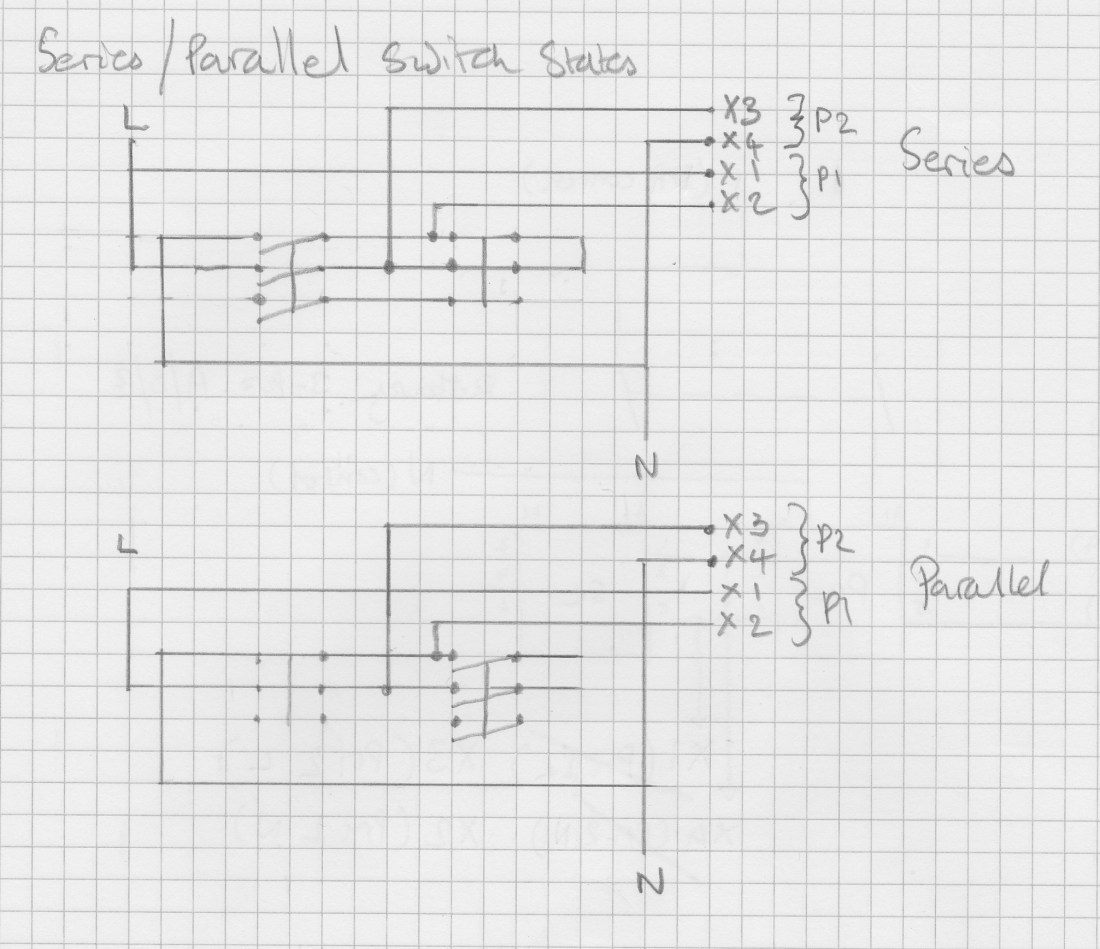
The sketch above shows the contactor based S/P switch in both the series and parallel states. In the first case, the two “outsides” of the transformer (X1, X4) are tied to live and neutral respectively, and X2 and X3 are shunted together via the right hand (series) contactor. In the parallel state, the series contactor opens and the parallel contactor closes, linking X2 to neutral and X3 to live. The third poles of the two contactors are unused in this application and remain unconnected.
The physical connections to the contactor package are easily derived from the circuit diagram:

The live and neutral supplies to the series/parallel switch are taken from the main bombarding contactor outputs: this provides a two pole disconnect which has the benefit of both fully isolating the external circuit and spreading the disconnect load across an extra pair of contacts (reducing wear and breaking capacity requirements).
The bombarding circuit is controlled by two main switches: a foot switch used by the operator to engage the high voltage circuit, and a keyswitch lockout to prevent the system from being activated accidentally (in fact there are two further switching points that disable the bombarder: the 10KV/20KV selector has a centre “off” position, and an external ballast bypass switch allows the entire circuit to be disconnected for maintenance). The footswitch links are brought out to a pair of terminals in the lower portion of the cabinet to allow it to be placed externally and removed for maintenance.
These are simply wired in series with the coil of the main contactor: all switches must be engaged to make the bombarding control circuit live.

The arrangement of the bombarding control switching is shown in the above sketch: in practice, several minor changes were made in building the final system. The “arm” switch in the bombarding control chain was removed (since the 10KV/20KV switch also provides this function), and the S/P switch was implemented with the pair of contactors described above rather than a single DPDT unit.
In addition to the two pole main 115A bombarding circuit, a normally open auxiliary contact block is attached to the contactor to switch the HT live warning beacon and front panel indicator.

The contactor used is a Schneider Tesys-D LC1D, a three-pole, 115A AC3 contactor with front and side auxiliary block mounts.
110V auxiliary supply
Because my vacuum pumps and some other devices are designed to run on 110VAC I needed a transformer to step down the UK 230VAC nominal voltage to something suitable for these loads.
For testing I used a consumer step-down autotransformer which provides a pair of standard NEMA US-style sockets.
For the cabinet build I decided to mount a transformer internally and to use this to power all the 110V loads, rather than supplying 230V to them and putting an external transformer in between. This gives a neater build and reduces cabling underneath the pumping bench.
The 110V loads are not particularly demanding: the diffusion pump is around 100W and entirely resistive (the small muffin fan has very little inductance), and the mechanical vacuum pump is only 400VA (full load current at 115V/50Hz is 8.8A). To allow for the nearly 9A start-up current I decided to use a transformer able to supply around 1000VA.

I decided to use a Legrand 0-442-68 1000VA model, RS stock number 535-7856. This transformer has a multi-tap primary allowing it to be used on 230V and 415V supplies and a dual secondary that can be used as either two separate circuits, or a single (parallel) circuit to use the maximum available current.
I based the transformer dimensioning on the estimated start-up current for all loads starting simultaneously: in the end this was a mistake as the transformer has a similar built-in tolerance and can carry up to 2000VA for short periods. It’s larger than it needs to be and generates a fair amount of heat when running (but I can now add two additional 110V vacuum pumps without needing to upgrade!).
The transformer supply is fused from the main fuse panel and individual loads have their own fuses according to the load capacity.
Auxiliary load switching
The auxiliaries make up all the other minor loads needed to keep the shop running: the vacuum pumps, air blower, spark tester, extractor fan, lights and other bits and pieces.
Some of these loads should be powered all the time (for e.g. the spark tester), while others are switched on and off manually. The extractor fan is an exception since it should run when any of the loads that generate fumes or heat are running: the air blower for the burners and the vacuum pumps.
Rather than having mechanical on/off switches on the front panel I decided to use push-button green and red start/stop controls like those you would find on a direct on-line or DOL motor starter panel. This requires the contactors or relays used for these loads to be configured in a latching fashion: the start button starts and latches the load, and the stop button interrupts the latch. For the small loads we are considering here we can generally get away with a simple feedback mechanism: the live output of the relay is wired back to the coil input, causing it to latch until either power is removed or the feedback link is interrupted.
Note that for larger inductive loads it is important to use a two pole contactor and to separate the feedback from the load: otherwise the inductive kick caused by the load disconnecting may be sufficient to keep the relay coil energised and prevent the circuit from opening (or worse: current may begin to oscillate between the coil and load causing rapid opening/closing of the contacts and generating large transients, potentially damaging the relay contacts or coil).
A similar (but much smaller) kick also occurs when the relay or contactor coils are de-energised. The transients produced by the kick may cause electromagnetic interference (EMI) as circuits switch so this induced current is allowed to dissipate through a circuit known as a snubber. The snubber either shunts the reverse voltage across the coil, or provides an impedance to damp large transients. Different forms of snubber exist for different applications (e.g. a simple diode shunt wired across the coil usually suffices for DC relays). For AC uses a series RC circuit across the coil is often used. Many contactors and relays for switching industrial loads include some type of built-in snubber avoiding the need for additional external devices: check the datasheet for the model in use to determine if this is the case.
In our case the switching of the auxiliary loads is slightly complicated by the fact that there are both 230VAC and 110VAC loads to consider. To simplify the design and cabinet wiring it was decided to implement a pair of busses or power rails, one for each voltage level. These are supplied by a common link (from the 110VAC step down transformer via the fuse panel for the 110 circuit and directly from a 15A feed on the main fuse panel for the 230 side). The advantage of using this arrangement is that each voltage level is cleanly separated out into a separate part of the cabinet, with common live and neutral rails for the attached loads. This also simplifies the implementation of the emergency stop switching which we will look at in a later section.


The rails supply power to each load relay, with the relays switched from the panel controls. The control wiring for each circuit uses the voltage level of the respective load (i.e. 110V loads have 110V control switching). One exception is the extractor fan: since it must come on when either the blower (230V) or the vacuum pumps (110V) are running, it requires two relays: one 110V and one 230V: if either relay is powered the fan receives power.
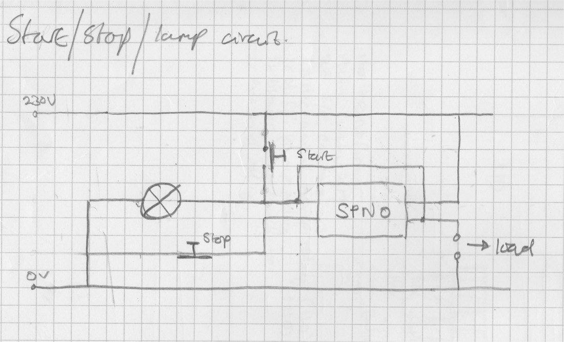
The diagram above shows a simple 230V start/stop circuit including an indicator lamp and using a direct feedback link from the load side to the relay coil. A pair of switches start and stop the circuit: the start button is a momentary normally open type, and the stop switch (placed in the coil neutral line) is a momentary normally closed model. This arrangement is adequate for resistive loads and small inductive loads (for example the extractor fan) but large inductive loads like the blower motor should use a double pole contactor and separate load and feedback links. No snubber is shown: either a device with a built-in snubber or an external RC snubber may be used.
For the three manual loads that we want to switch (the air blower, mechanical vacuum pump and diffusion pump), we have two 110VAC loads and one 230V: the circuits used for each are very similar but draw from the respective power rail according to the load voltage.
 The layout of the two busses and the start/stop circuits is shown above. The thick vertical bars represent the live and neutral sides of the two power rails and the relays for the vacuum pump (VP), diffusion pump (DP), and blower motor (BM) are shown along with their associated switches and indicator lamps. In the final build the blower motor relay was replaced with a two pole model to avoid the inductive kick effects described earlier.
The auxiliaries use simple Finder DPST (double-pole, single throw) or SPNO (Single-pole normally open) DIN mounted relays, for example, RS stock number 159-789. These are simple and compact models that occupy a single DIN rail slot, handle up to 20A continuous load and are suitable for lightly inductive loads. Versions with 110VAC and 230VAC coils are used in the respective load circuits.
The panel controls and indicators are all from the Schneider XB4 range of modular lamps and switches. This is a range of contact blocks and lamp holders, push button, emergency stop, and key switch heads, and other accessories that can be combined in different ways to produce a finished system. The parts are easy to use and have a nice look and feel: it’s easy to produce a fairly professional looking result that works well and is simple to maintain.
Emergency stop switching
The emergency stop switch is a safety function: it must immediately and certainly disconnect all loads (especially the high voltage bombarding circuit), and maintain this state until the operator performs a manual reset.
There are a number of ways to implement this task, all relying on the use of an emergency stop loop. The loop is a set of series wired normally closed (NC) switches that interrupt the circuit and latch whenever a stop button is pressed. Stop buttons are available with a variety of reset mechanisms: twist-pull and keyswitches are both common. Using passive (interruption) signalling makes the loop inherently safe in the event of a wiring fault: any disruption of the loop triggers the stop rather than creating a situation where the emergency stop will not be effective.
I wanted to have a pair of emergency stop buttons, one mounted on the control panel and one on the opposite side of the room by the bombarding bench. This scheme is easy to extend by simply adding additional switches (for example to provide a third switch adjacent to the entrance to the room).
Since the system uses split 110/230V rails it is necessary to interrupt both power sources in order to shut down all loads. Again there are several ways that this problem can be approached: for example, a master 230V contactor that switches a slave 110V unit. Alternately a single four pole contactor can be used to disconnect the entire supply from both the 230V and 110V rails simultaneously. This interrupts all control signals and forces all contactors in the system to go open-circuit.

The two schemes are sketched in the above diagrams: in both cases the ES contactor coil is connected to the supply via the emergency stop loop. The top diagram shows a bus-switched design with a four pole contactor lifting the live and neutral supplies to both power rails. The lower diagram shows a master/slave arrangement with the 110V slave chained off the 230V rail (when the ES is activated the 230V bus will lose power, causing the 110V slave to also open).


The final build took the bus switching approach: this reduces the number of contactors required as well as the wiring complexity and safely achieves the goal of disconnecting all devices in the event of an emergency stop being raised.
In order to have an indication that the emergency stop has been triggered another auxiliary contact block is used on the ES contactor. This time a normally closed (NC) type is used: the main contacts must be closed to energise the two power rails and this causes the ES warning lamp to be extinguished. When the ES fires and the main contacts open the warning lamp contact closes and lights the indicator.
The panel mounted emergency stop switch is a Schneider XB4 40mm turn-to-reset type and the wall mounted switch is an Apem 40mm twist-to-reset type in an IP65 housing.
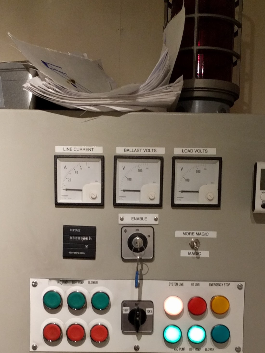
Metering and monitoring
We’ve looked at some of the basic indicators as part of the circuits they occur in: the load indicator lamps for the pumps and blower, HT warning beacon, and the emergency stop lamp. There is also a simple “System Live” indicator wired across the supply to show clearly when the panel is live.
As well as these basic indicators it’s helpful to have some insight into what’s happening in the main bombarding circuit. Although the bombarder is equipped with a bombarding milliammeter (actually two, get me!), since I am using a home-built choke and other equipment I wanted to be able to see the load voltages and current from the line (mains) point of view.
There are two voltages of interest here: first is the voltage across the load (bombarding transformer) itself: this gives an indication of the voltage being developed across the high tension side of the transformer, and secondly it is useful to monitor the voltage drop across the ballast (slide choke). See Ballast to basics and All Choked Up for more details on the electrical characteristics of the choke used.
The two voltages actually have a well-defined relationship: the choke is in series with the transformer primary winding and together they form a voltage divider, with the voltage dropped proportionately across the two devices according to the ratio of their AC impedance. Because of this fact it is always possible to determine one voltage when the other value is known: it is simply the complement obtained by subtracting the first reading from the line voltage. Two meters are provisioned to allow the two values to be quickly and easily read while the system is in operation.
The two voltages are referred to in circuit diagrams and labelling as 

The voltmeters used are 68mm GMW 250VAC analogue panel meters, RS stock number 201-925.
Due to the high power levels seen in the primary side of the bombarding circuit is is impractical to meter the current directly: a direct-reading 100A AC ammeter would be very large and costly, and the panel wiring needed would be bulky and impractical (as well as introducing additional potential failure points into the circuit).

The solution to this is to use a current transformer (CT) that uses induction to transform the current in the circuit under measurement to a value that can be reasonably metered.
Current transformers are available in a range of types and ratios and provide an accurate measurement ratio when used within their design parameters. Current from the measured circuit is normally coupled to the transformer by placing it around the conductor: effectively a simple one-to-many transformer. The hole through which the conductor under measurement passes is known as the window.
Rogowski coils and Hall effect sensors provide alternative current sensing options that are more flexible both physically and electrically than a conventional CT, but these extra capabilities are not needed for the simple measurements in this application.
Split core and flexible versions are available that can be placed around a conductor without disconnecting it and are useful for temporary field and fault-finding measurements.
Current transformer ratios are normally expressed as 
It is also important that a CT is always connected in-circuit when the measured circuit is energised. Never leave the terminals floating when a current is flowing through a conductor in the transformer’s window: otherwise the large turns ratio may cause a high potential to develop between the CT terminals possibly leading to insulation breakdown and other hazards
The CT used in this build is a Hobut DIN mounted 50/5 (RS stock number 331-339), and the ammeter is a GMW 50/5 100A meter (RS stock number 201-896) with a non-linear scale: a linear 0-50A scale occupies approximately 75% of the meter deflection and the remaining space contains marks up to 100A. This is well matched to the current 63A supply used in the workshop that allows about 80% of the bombarder capacity to be used. If the supply is upgraded in the future the CT and panel meter are exchanged for 100:5 equivalents by disconnecting the bombarding feed at the fuse housing.
Protection
Since we’re dealing with fairly high currents and a range of different mechanical and electrical loads it is important to take steps to protect circuits from over current conditions that may arise. Excess current may flow either due to some component or circuit being overloaded or due to a fault presenting a hard short-circuit on some path. It is also important to detect earth faults where current unexpectedly flows through the third (earth) conductor.
A separate consumer unit provides basic earth fault and overcurrent protection in the form of an RCD (residual current device) and MCB (miniature circuit breaker). These provide system wide protection from both gross (short-circuit) and slow overload faults.

Further protection is then provided on a per-circuit basis within the control cabinet. Two DIN rail mounted fuse panels are located inside the cabinet: one above the main incomer and an auxiliary panel next to the emergency stop contactor. The first provides fused power supplies to loads and internal busses and the second contains the separate emergency stop fuse and metering fuses.


To prevent a mechanical failure in either voltage meter from resulting in a short circuit across the ballast or bombarding circuit each circuit has a separate low-current fast blow fuse located in the auxiliary fuse panel.
The main bombarding circuit is protected by a separate cartridge fuse: the cartridge holder is rated for 100A but is currently fitted with an 80A fuse.


Fuses rarely blow in normal operation: a couple of the smaller fuses blew in the first few months because they had been under-specified for the attached loads. In order to avoid down time in the event of a failure a complete set of replacement fuses is kept in a box inside the control cabinet.
Physical layout and cabling
With all of the circuit considerations decided on it’s necessary to plan the layout of the various circuits and components inside the cabinet. As mentioned in Standing in the way of control, the cabinet had some existing DIN rails and cable trays and these were reused in the build.
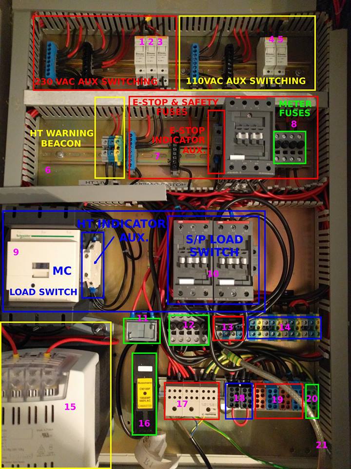
The two main power rails (230V and 110V) are placed in the upper-left and upper-right row respectively along with their associated load relays. Power is supplied to the rails via the main incomer, fuse panel and emergency stop contactor.
In the next row down is the HT warning beacon terminal block, emergency stop contactor and metering fuses. Power is routed to the rails via the output of the ES contactor, and the metering points from the terminals in the lower part of the cabinet pass through the fuse block on the way to the panel mounted meters.
Next comes the master contactor, HT indicator auxiliary block and series/parallel load switches. The load volt meter measures across the blue and red tagged cables feeding into the left hand (series) S/P switch contactor and the ballast meter connects to the ballast send/return terminals labelled 18 at bottom right (the terminals are shown shorted in the above photograph for testing purposes).

At the bottom is the 110VAC transformer powering the 110V rail, and two rows of terminal blocks adjacent to the main bombarding fuse and bombarding current transformer. The terminals are divided into four main areas: the incoming feed from the consumer unit, send and return for the ES loop and foot switch, power out to the auxiliary loads, and the ballast and transformer connections for the bombarding circuit.


The incoming power supply terminates in a Weidmuller 175A DIN mounted 21 way distribution block, RS stock number 837-1048. This provides live, neutral and earth channels with 35mm² input terminals and a range of output terminals (6 per channel, up to 16mm²). Power is then taken from the distribution block to the fuse panels and bombarding fuse.
The terminals used for the bombarding circuit are Phoenix Connect UDB series terminal blocks, rated for 101A and 1KV: they are available from RS in the conventional live, neutral, and ground colours as well as other colours for specific designations (e.g. the ballast send/return use black terminals). These are really neat snap-on terminals with one 16mm² terminal on either side, and one smaller terminal that is ideal for attaching metering points or other auxiliary circuits: the voltage metering connection to the ballast circuit uses this feature. The brown, blue, and green 101A parts have been discontinued by the manufacturer, but replacement 125A models are available from RS in the non-fused DIN rail terminal category.
Control send and return and auxiliary load terminals are standard ABB MB series non-fused DIN rail terminals. They are rated for 10mm² stranded cable and 10A at 600V.
OK: that covers most of the organisation, design and implementation of the bombarding and auxiliary load controller: it’s not the most exciting topic, but it is a fundamental part of a working neon plant and having a reliable and efficient means to control all the different loads makes for an easy to use and comfortable working environment.
If I’ve missed anything out or if anything about the controller is unclear feel free to get in touch via the comments or contact information and I’ll try to fill out the missing details.
Join us in the next post when I’ll try to get back to hot glass and pretty lights!
