I realise we haven’t really gotten into the details of the diffusion pump on the blog so far (or any vacuum pumps at all to be honest), but since I needed to dismantle my pump for a service this week it seemed like a good time for a post on the subject of the care and feeding of these clever little machines.
While the pumps were down I also took the opportunity to change the oil in the mechanical pump so we’ll look at the steps involved in that job too.
We’ll have a quick look at how the pump system works and what it’s doing for us in the bombarding process and then run through the steps to clean and re-install a glass bodied pump in an existing set up, and a typical oil change procedure for a rotary pump.
I’ll quote details for the SVP standard flow pump that I use (also valid for Precision Neon Labs pumps), as well as my Vacuum Research rotary pump, but the procedures are largely the same for any glass diffusion pump or mechanical roughing pump used for neon work.
Pumped up kicks
The vacuum system is one of the three essential components of a neon processing system (the other two being the bombarder and rare gas delivery lines). Its job is to reduce the pressure inside the pumps, manifold, and any attached unit to a hard vacuum.
The lowest pressure a given system can achieve is known as the ultimate vacuum of that system. Since an absolute vacuum cannot be achieved no system ever reaches an ultimate vacuum of true zero: for neon pumping work an ultimate vacuum of less than 1mTorr (approximately one millionth of normal atmospheric pressure) is needed and with modern equipment a pressure of 0.1mTorr or even less is achievable.
All modern neon pumping systems use a multi-stage pumping system: a mechanical roughing pump is used to create a rough vacuum (less than 50mTorr but often 2.5mTorr or less for modern gear), and a separate diffusion pump inlet further reduces the pressure in the manifold to less than 1mTorr. Mechanical roughing pumps for neon use are typically two stage rotary vane pumps.
In this way the pumps work together to deliver the required pressure inside the system: the diffusion pump cannot work without the rough vacuum and exhaust pumping provided by the mechanical pump, and the mechanical pump alone cannot achieve the necessary low pressure or high pumping speed
The mechanical pump is connected to the rest of the pumping system through the foreline: a glass, metal or rubber tube through which all the gasses in the system will be removed. The foreline may also include stopcocks to allow isolation and venting of the pumps. Traps are sometimes installed in the foreline to collect contaminants but these are not required for normal processing of newly made neon units. Shops doing significant repair work may add traps to handle the greater contamination levels that may occur in this type of job.
Technically the two pumps are said to operate in different flow regimes: the mechanical pump is effective in the viscous flow regime. This corresponds roughly to pressures between atmospheric and the ultimate vacuum of the mechanical pump alone (low-mid vacuum). At these pressures the air is kinda thick and gloopy and can easily be scooped out of the system by the rotary pump since it behaves like a fluid.
Beyond this range, and into the high vacuum or molecular flow regime things get a bit weird as gas molecules become few and far between. The mean free path (the distance a gas particle travels before colliding with something) becomes larger than the vacuum vessel itself: at this point the gas no longer behaves as a fluid and instead acts like a bunch of tiny particles pinging around on their own and bouncing off the walls of the vessel in random directions.
The gas can now only move through the system by this slow process of diffusion. This makes conventional pumping impossible and is the reason that a multi-stage approach with a special high-vacuum pump is required: enter the diffusion pump.

A diffusion pump is a simple device having no internal moving parts. Pumping is achieved by entraining gas particles in the intake column into a supersonic jet of vapour created by boiling a special silicone based oil in the vessel.
The jet forms a barrier against which diffusion is impossible: any particles entering the base of the pump from the manifold will be carried upward toward the mechanical pump where they accumulate and are pumped out through the exhaust.
A cooling column in the pump exhaust allows the pump fluid to condense and flow back down into the boiler section, repeating the cycle continuously. A small fan is normally directed at this section of the pump to assist the process.
You can see this occurring in the short video above: if you look closely at the neck of the pump around the bottom of the temperature gauge (the white label with the dark coloured boxes) you can see the pump oil “surging”: waves of oil that have condensed in the neck flow back down and are temporarily pushed back up by the force of the vapour jet. Eventually the liquid will always find its way back down into the boiler to repeat the cycle (unlike the gas molecules which are trapped and dispatched through the exhaust).
Diffusion pumps for scientific or industrial use (like the examples in the Wikipedia article) are constructed using the same mechanism but a different arrangement of the component parts: multiple jets are fired downward from a central column with the inlet stack at the top of the main body and the exhaust near the bottom of the heated vessel. This looks reversed in comparison to a glass bodied neon unit but the operating principals are the same.
Scientific units are also typically metal bodied and are water-cooled rather than air-cooled. They can be used for neon but are more complex to install and operate (since they require a constant source of cold water when running). They are only needed in special situations where a glass pump would be too fragile, or when very high pumping capacities are called for.
The diffusion pump adds two major benefits in the neon shop: it lowers the ultimate vacuum of the system (since it can clear residual pressure from the system once the molecular flow regime has been reached), and it greatly increases the high-vacuum pumping speed of the system since the pump is able to concentrate and expel the remaining gasses once they diffuse into the manifold outlet rather than relying on them diffusing all the way through the foreline and back to the rotary pump.
This translates to faster and more effective operation and ensures the production of high quality tubes with minimal contamination and the expected long service life of a neon unit.
Aside from periodic oil changes, in normal operation diffusion pumps are virtually maintenance-free: the only troublesome aspect of their operation is keeping the temperature in the boiler at the correct set-point. To low a temperature will greatly reduce the pumping efficiency while too high a temperature will lead to excessive oil loss and the formation of silicate crystals in the intake stack. Most pump controllers do not have a thermostat and so periodic monitoring and adjustment is required (especially in a non-climate controlled shop).
Grime time
The frequency of maintenance for neon vacuum systems depends on several factors: the volume of units being processed, the level of contamination it handles (both air and dirt from processed tubes), and the general cleanliness of the environment since dust, dirt and soot from the fires may enter the vacuum system from the surrounding air.
Common quoted figures are typically every six months or every 4-6 thousand units processed (whichever is reached soonest). Additionally, the diffusion pump oil must be changed immediately if it appears degraded (a colour darker than a pale yellow-amber, or having dark black spots or tarry patches on the pump walls).
Another less common sign of trouble in a diffusion pump is the formation of what appear like small white or grey salt crystals in the intake stack (usually close to the manifold connection). These form when overheated silicone oil degrades and are always a sign that the pump has been run too hot for an extended period: the pump should be immediately taken out of service, thoroughly cleaned, and filled with fresh oil before continuing.
I managed to let my pump reach a point where it was showing all these signs: silicate formation, amber pump oil, and tiny black patches on the boiler walls. Definitely time for a clean-up!

I forgot to take a picture of the spent fluid in the pump before draining it, so here’s one of the fluid in the collection vessel. Notice the pale yellowy-amber shade: on its own, this level of change is probably not sufficient to warrant an oil change but with the other signs my pump was showing (silicates and black marks in the boiler) it was definitely overdue.
When inspecting the oil it’s important to drop the heating mantle away from beneath the pump: the inner surface of the mantle often discolours in use and this makes it difficult to get a good sense of the oil colour. If you’re still having trouble with the mantle out of the way try holding a sheet of plain white paper up behind the boiler to get a better contrast.

As well as some minor oil degradation I had clear signs of overheating in the form of small silicate crystals near the top if the intake stack. This occurred in the first few months of operation (at the start of the summer) as I was trying to get the boiler temperature adjusted.
I now tend to err on the low side with the temperature set point, and increase the heater power an hour or two before processing units if it’s below the ideal point of 80ºC. Once I’m done I’ll drop it down again to avoid overheating when the system is unattended.
Proper preparation
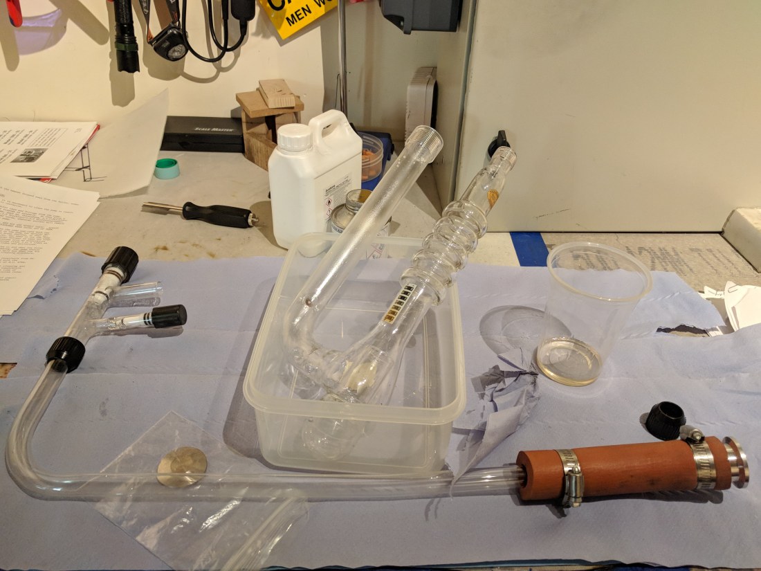
It’s a good idea to be well prepared for this job: you’ll need adequate supplies of spare parts and fluids, cleaning supplies, gloves and other bits and pieces.
My regular cleaning kit consists of the following:
- Large rectangular plastic tub (spill tray)
- Small plastic tub (waste oil pan)
- Small plastic tub w/snap on lid (part wash)
- Clean, dry cardboard box large enough for all glass parts
- 0.5L Pyrex® measuring jug
- Large (10cm) and small (5cm) plastic funnels
- 10cc plastic disposable syringes
- Soft pointed pencil (glass pencil, NOT grease pencil!)
- 10-25x hand lens or jeweller’s loupe
- Plastic pint glasses (waste pump fluid)
- Screwdrivers, spanners etc. to disassemble clamps and flanges

I also get through a fair amount of consumables:
- 1 roll white lint-free paper towels for cleaning and covering glass
- 1 roll cheap blue “workshop” roll for cleaning up spills
- Plastic sheeting or bin liners
- Blue nitrile gloves (lots)
And lastly you’ll want a bunch of unpleasant, violent, and highly toxic solvents to make the job go with a real bang:
- 100% Isopropyl alcohol (e.g. Servisol switch cleaner)
- High purity acetone
- Glass wash solvent
If you have access to an ultrasonic cleaning bath they also make a good job of the smaller glass parts like the foreline adapter.
Ideally the acetone should be analytical reagent grade (“analar”) with an evaporation residue of 0.001% or less. Acetone sold for cleaning as “99.5% pure” (or better) is typically usable but a quality laboratory solvent is preferred.
The glass washing solvent you use is a matter of choice: if the manufacturer of your pump recommends a specific fluid it’s best to use that. In most cases though a list of acceptable solvents is provided. For my SVP pump it includes:
Chloroform, 1,1,1,-trichloroethane (Carbo-Trichlor), Trichloroethylene, 1,1,2-trichloro-1,2,2 trifluroethane (Freon™), chromic sulphuric acid, laquer thinner etc.
These are all lovely things to throw around the house or down the drain. They also eat ozone at twenty paces. The ‘etc’ here could also include things like tet (carbon tetrachloride, tetrachloromethane) a dry cleaning solvent now being phased out due to its severe neuro and hepatotoxicity.
Luckily I didn’t have any of these in the house but I did have some reagent grade tetrachloroethylene: also known as perc. This is another dry cleaning solvent (and is used as a thinner for neon blockout paints) but it has a much better safety profile than tet: it is non-flammable and has moderate to low toxicity at normal exposure levels.
At temperatures above 300ºC it can break down into very toxic products so some care and good ventilation is still essential. If you have to work in a confined space consider using a mask or full face respirator with a filter rated for organic solvents.
Perc isn’t as fast a solvent as the others so more washes or longer washes may be needed to get the same result. It’s also slightly more viscous but washes away easily with acetone.
Service wash
Once the decision has been made to strip down the vacuum system for maintenance it’s time to shut off the pumps and carry out an orderly shutdown of the whole system.
On my set up I use the following steps to shut down the pumps and prepare for dismantling:
- Close the main stopcock to the manifold.
- Turn off power to the heater but keep the fan and rotary pump ON.
- Wait for the diffusion pump to cool down to 60ºC or less.
- Close the isolation stopcock at the foreline adapter (if fitted).
- Turn off the mechanical pump.
- Once the pump is close to room temperature slowly and carefully release the vacuum by admitting air through the foreline adapter vent stopcock (if fitted), or by opening the manifold main stopcock and using the manifold vent.
One way to do the final step is to cover the vent hole with a fingertip, open and then close the stopcock, and repeat this two or three times before slowly opening the stopcock fully (with the finger removed): this avoids causing a pressure shock in the pump body due to the high pressure inrush of air.
A foreline adapter that allows the mechanical and diffusion pumps to be isolated, and that allows air to be introduced to the diffusion pump body is helpful for this task, since it means that the manifold stopcock can remain closed and the manifold will be kept under partial vacuum throughout the entire procedure, reducing degassing times when the system is put back into use.
If like me you need to use your pattern bench for the clean up you may want to cover it with a layer of plastic sheeting or a bin liner before starting: this will stop any oils or solvents leaking through from the paper towels and soaking into the bench top or covering. Silicone oils and hot glass are a bad combination. What ever surface you are working on put down a layer or two of paper towels or workshop roll in case of spills.
Place the spill tray on top of the paper ready for the pump parts, and put a waste oil container (I use the plastic pint glasses) inside it to catch the pump oil.
With the pump cool enough to handle begin loosening the compression fittings or flanges connecting the pump to the manifold and foreline. If the foreline contains glass tubing or adaptors now is a good time to take those apart for cleaning too. Loosen any clamps retaining the pump but ensure the pump is still secured for the moment.
Put on a pair of nitrile gloves and completely undo the compression fittings, flanges, and clamps. Drop the heating mantle away with one hand, while supporting the pump body with the other, and very carefully lower the pump until the inlet and exhaust stacks are clear of the manifold and foreline connections respectively.
Take extreme care with this step to avoid ‘binding’ either connection: if the inner tube of a threaded glass compression fitting is not absolutely straight the edges of the tube may contact the walls of the containing tube and bind: this is the easiest and most common way to damage this type of vacuum fitting and repairs may be very costly.
While holding the pump with one hand on either stack carry it over to the bench and tip the exhaust port of the pump (the smaller port at the top of the cooling ribs) over the waste container. It may take a minute or two for the oil to drain completely due to the ridges in the exhaust but it’s not essential to get everything out at this stage: any residue will be cleaned off with the solvents later.
Put the waste fluid to one side for disposal and set the pump down in the spill tray. Inspect it carefully for any soiling, crystal accumulation, or other dirt. It’s common to find a layer of brownish black dust on the hot parts of the pump: the cooling ribs, neck, and especially the vigreux ‘fingers’ in the exhaust stack.
This can be removed from the outer parts with a paper towel or polishing cloth. To remove accumulated dirt from the underside of the ribs or the vigreux, use a small brush or a soft pointed tool (like a soft glass marking graphite pencil) and a scrap of tissue or paper towel.
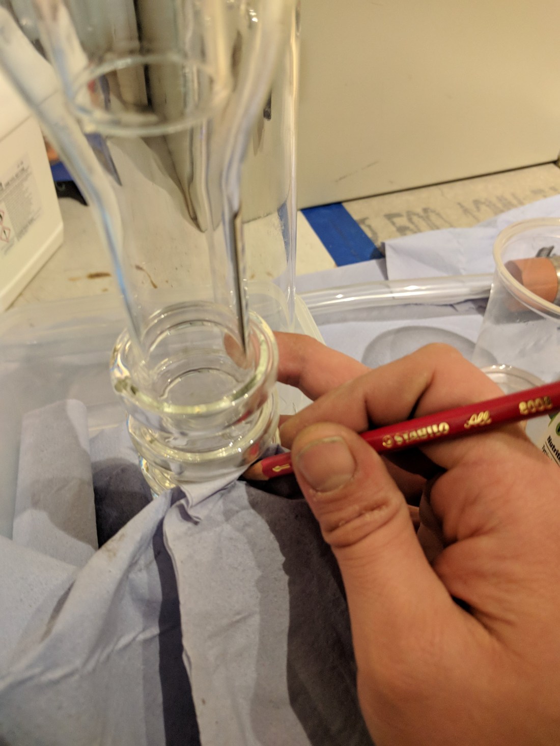
Once the outside has been thoroughly dusted and wiped down it’s time to start the internal cleaning. Before doing that, take the cardboard box and line the bottom with paper towels and put it aside somewhere out of the way so that the glass can be put into it to dry.
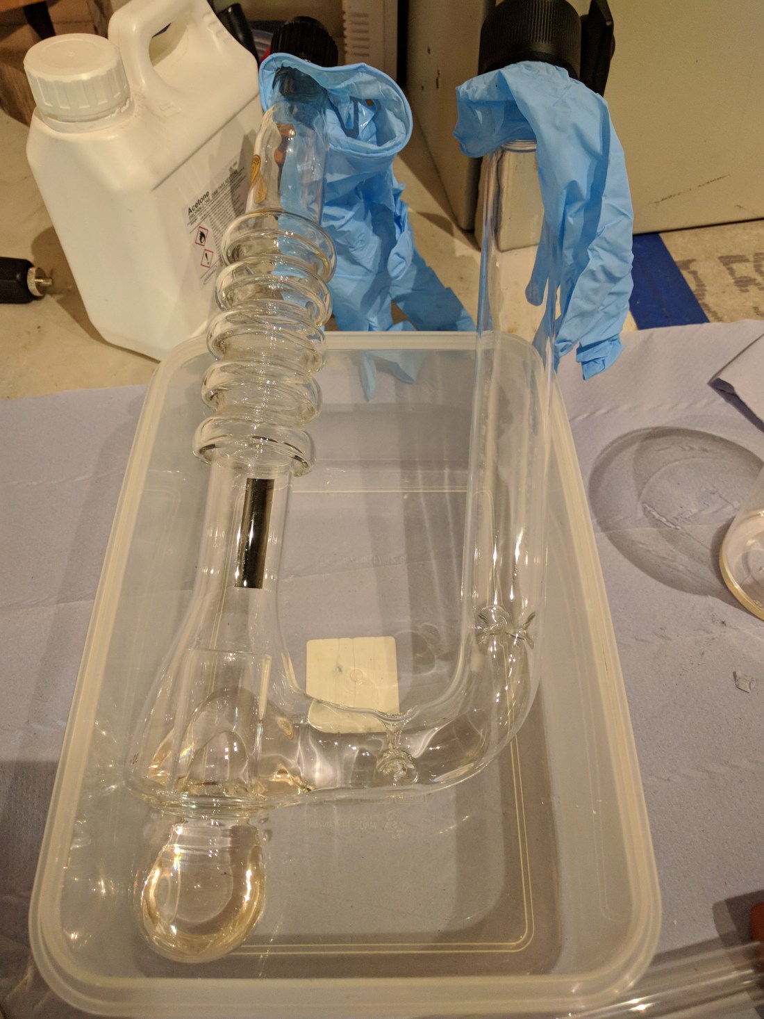
If you’re organised, you will have already obtained matching stoppers for every port on your manifold and pumping system. If you’re like me you may have to improvise. I didn’t have any bungs to fit the intake and exhaust ports so to block them off while doing the solvent wash I used a couple of nitrile gloves, gently held down using the corresponding compression cap.
This works well enough although it isn’t ideal. Nitrile is high vacuum safe, and is compatible with perc, but it is weakened by acetone. For this reason when it came to rinsing, I simply held the gloves in place: using the caps tends to tear the gloves into tiny scraps that are annoying to clean up.
A better solution if you have the time and glass tubing is to make “test tube” stoppers that will fit the compression caps and o-rings.
Pour a little solvent into the pump, half via the exhaust, and half via the intake. The amount needn’t be exact but it should be around one to two times the normal fill of the pump (30-60cc for mine). Cap both ports of the pump and then shake gently for a few minutes. Alternate through up-and-down, side-to-side, and swirling motions (alternating the direction of the swirl every few moments) for the best and quickest results.
Pour out the used solvent into a container for disposal and repeat the whole process three to four times, or until the glass appears crystal clear and completely clean. Use a hand lens to inspect the boiler area of the pump and check for any remaining dirt or residue.
Once the solvent wash has been completed, switch over to acetone: again, pour the solvent in through both ports of the pump and gently but thoroughly agitate the pump to remove all residue of the cleaning solvent. Repeat the acetone rinse three or four times and then very carefully shake the pump upside down to get rid of as much acetone as possible.
Place the pump inside the cardboard box and cover the open ports to keep dust out. Close the box and leave it to dry. Acetone should dry very quickly: even at 15ºC it will easily be dry within an hour or two.
Pay careful attention to any stopcocks as moisture or solvents may take longer to evaporate from the throat of the valve. Clean, dry air or better, a gently heated drying cabinet, may be used to help speed up drying but for acetone shouldn’t be needed.


Repeat the washing process for each glass component and then set to dry alongside the pump. For any components with a stopcock pay careful attention both when washing, to ensure solvent flows in and out of the barrel, and when drying to be certain all solvent has evaporated from inside the body.
Oil rush
While all the glassware is drying it’s a good time to change the oil in the mechanical pump. Check the manufacturer’s recommendations and consider changing the oil once or twice a year depending on use.
The mechanical pump maintenance is simpler since it doesn’t normally require the system to be dismantled. Again, the procedure used here is suitable for my pump and most similar mechanical pumps in use, but consult the procedures for your own equipment in case they differ.
Since the rest of the vacuum rig was in pieces I capped off the intake to the pump with a spare K-flange blanking plate and just ran the pump against that (this is a perfectly fine thing to do – it is a vacuum pump, after all!).
Warm the pump up by running it for at least thirty minutes and then place a collection pan underneath the oil drain plug. Turn the pump off and loosen the oil filler cap. Undo the drain plug and quickly pull it away. Oil will flow out into the pan. Initially it may jet out several inches but as the flow subsides to a trickle it will just pour straight down from the plug hole. Make sure the pan is positioned for both!


Take a look at the oil coming out to get an idea of its condition: clear oil is new or nearly new, but a pale amber colour is also fine. If the oil is darker amber or yellow, cloudy, or has particles floating in it then it’s definitely time to change and the pump will probably need a thorough flushing to get it back to peak performance.

My oil was well past its best so it’s a good job I got on with it!
You can use pretty much any glass, plastic, or metal container to dispose of the oil. Check with your local recycling service to find where you can dispose of oils and solvents.

After the oil has drained, measure out just under half the pump’s capacity (mine is 700cc, so I used about 300) of fresh pump oil and then put the drain plug back in and fill the pump up to the “minimum” oil level. Run the pump for ten minutes and then repeat the drain procedure. Keep repeating the flushing procedure until the oil that comes out looks like the right hand bottle in the photo above.

When the pump starts with a fresh fill of oil it will often make a funny thumping noise as it pulls oil into the internal mechanisms. This is normal and nothing to worry about: as long as it settles down to its normal sounds within a few seconds everything is fine. If it doesn’t, check all caps and the intake are tightly secured and refer to the manufacturer’s troubleshooting steps.
As well as changing the oil, it’s a good idea to inspect the element of any installed oil mist eliminator. I use the SVP one supplied with the pump: it’s a small two part plastic device with a tubular filter element retained by a spring. The housing has K-flange fittings at either end for attaching to standard vacuum components.
Open up the housing and check the element visually: if it appears dirty, wet with oil, or otherwise degraded, replace it. Mine seemed pretty clean so I left it in place.
Reassemble the filter in the lower (pump) side, making sure that the spring and filter element slide over the ‘teeth’ inside the two halves of the housing and then reinstall the filter on the pump.


Wash’n’go
With the mechanical pump serviced and the glassware dry it’s time to put everything back together. In this case, the mechanic’s curse of reassembly is the reverse of removal applies: either reverse the steps you took previously, or follow the manufacturer’s install procedure again, to get the pump back into position.
For my set up that means putting compression fittings onto the manifold exhaust adapter and foreline adapter, filling the pump with 30cc of DC704 compatible diffusion pump oil, and then sliding the pump into place and tightening everything up.
Unfortunately at this point I noticed some oil had crept up into the manifold adapter and crystallized there: this meant a bit of a delay as that part was stripped out and subjected to the same solvent washing and drying.


I use a 10cc syringe to measure out the pump oil: it’s less fiddly than a small measuring cylinder and the syringe is about the size of the neck of the bottle the oil comes in so it’s easy to just pull up three shots and fill up.


I decided to re-use all the o-rings and compression caps since they appeared to be in good condition and I hadn’t had any problems with leaks on any of these connections.
O-rings are pretty cheap and I could have replaced them all but with normal use they should last for 2-3 years: I’ve also found some new o-rings that came “pre-dirtied”, so they needed cleaning before use anyway. I get mine from Eastern Seals now: they’re cheap, quick to ship, and they gave me loads of fridge magnets and coasters. The o-rings are clean too.
I clean the o-rings and compression caps using isopropyl alcohol: it’s a bit gentler than acetone and less likely to degrade the rubber. I put the parts to be cleaned in a clean plastic box with a snap-on lid (like a sandwich box) and then shake thoroughly for a few minutes. Pop one corner open and drain, lather, rinse, repeat.
It’s the easiest way to get o-rings and caps dust free and a final inspection with a hand lens ensures a good seal (any remaining dirt can be removed by rubbing the ring against a clean nitrile glove).


When reassembling Pyrex high vacuum stopcocks after cleaning a light coating of Apiezon-M grease should be applied to the upper two (sealing) o-rings. The tip o-ring should not be greased.

Do not use any silicone vacuum grease anywhere near a Pyrex manifold: it creeps through the system forming a monomolecular layer that is extremely difficult to remove. If a repair must be made the grease can contaminate the glass, causing it to become cloudy and weakened.
Once everything is fitted into place it’s time to fully tighten each compression fitting, check the pump is sitting vertically as it should, and then tighten all securing clamps and fixings.
The last step is to get everything back up and running. Close the isolation stopcock if fitted and turn on the mechanical pump. Once the pump sounds like it’s pulling a good vacuum open the isolation stopcock. The pump oil may bubble violently at this point: this is normal and due to dissolved and absorbed gasses in the fluid.
Once the pump noise returns to the vacuum sound turn on the heating mantle and fan and allow the pump to come up to temperature per the manufacturer’s recommendations.
Do not open the main stopcock to the manifold until the pump is at full operating temperature.
After a couple of hours of pumping my vacuum gauge shows a reading of around 1mTorr: since large parts of the vacuum system have been exposed to the atmosphere for an extended period it may require 24-48 hours of initial pump down to clear any remaining outgassing and be ready to process tubes.


So that’s it for this unscheduled detour into pump maintenance. In the next post we’ll get back to the exciting business of electrical control systems for neon workshops.
