A neon workshop contains a number of electrical systems to support the glass work and processing equipment: electricity powers the bombarder, air blowers, mechanical vacuum pump and the heating and cooling equipment for the diffusion pump, as well as a host of minor auxiliary loads such as gauges and the spark tester.
In this article we’ll take a look at some of the components that go into the controller for a neon workshop as well as some of the high-level design and practical considerations involved in putting together a working system.
This is another technical and in-depth article: don’t worry, I’ll get back to posting pictures of pretty lights soon.
As well as the number of loads to manage, neon work places a big demand on the electrical supply: as we found in the series of articles on current control for bombarding systems, at peak capacity line current may reach close to 100A for a single processing station working with large tubing and high-current electrodes.
All of this calls for an organised and integrated approach to connecting and controlling the various machines and appliances.
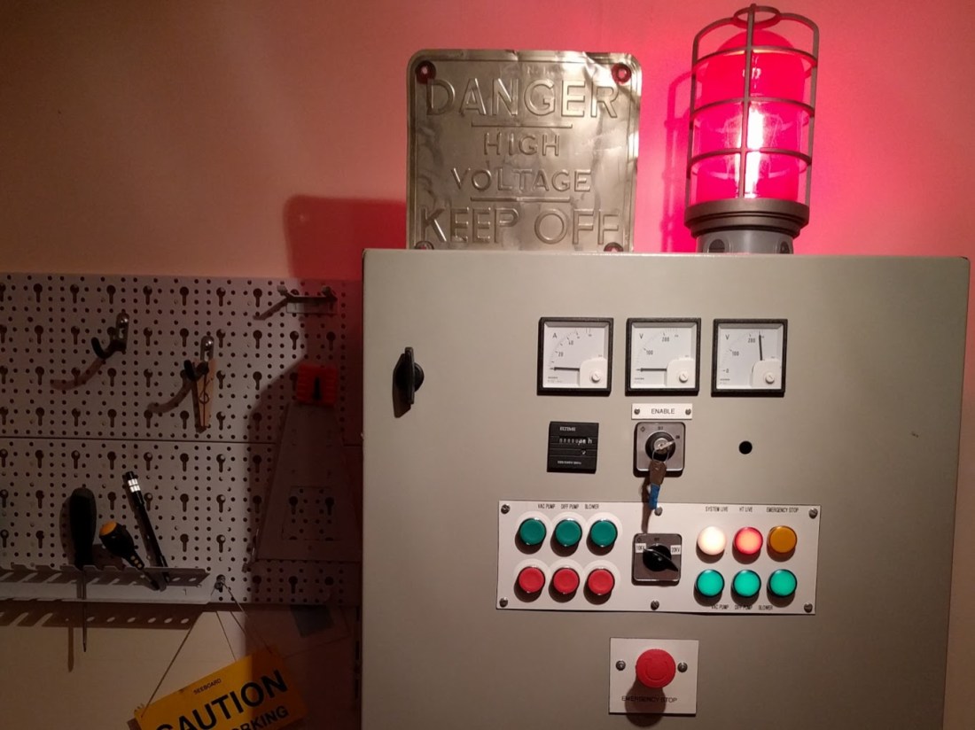
Enter the Fat Controller
Ever since I was a kid I’ve been fascinated by those huge industrial control panels you see in factories and industrial plants: all the red and green buttons, gauges, and blinking lights and the clever modular designs really appeal to me, but even I couldn’t justify putting something like that in the kitchen to run the toaster oven…
The downside of these types of clever, modular systems, is that they are normally purchased by organisations with very deep pockets. Major components like cases, pre-cut and drilled panels, and so on, are eye-wateringly expensive.
Not only that but it can be very hard to get hold of the complete range of models and accessories: in a typical industrial project a buyer will work with the manufacturer’s or reseller’s sales team to put together packages of matching components for the whole deal. Vendors who sell individual bits to consumers have much less vested interest in providing this kind of sales support and often just carry the best selling parts.
On the upside however, these systems have barely changed in three or four decades (save minor refinements like LED options on lighting elements): the basic DIN rail system for mounting components vertically, as well as the panel hole sizes for standardised switches, lamps, and other modules are exactly the same as those made in the ’80s or ’90s: you can even swap brand new modular lamp parts with their thirty year old counterparts.

The upshot of all this was that I decided to find something second hand that was close to the system I had in mind, and to modify or rebuild it accordingly.
Several weeks or months of eBay searching later I came across this second hand, 10KVA generator switch over panel in Glasgow. It’s designed to automatically switch between mains and generator power in the event of a supply failure.


The key points that made this a good base for the project were:
- Enough space to mount several large contactors and a transformer
- Large cut out for replaceable laminated mounting panel
- Removable top and bottom cable gland panels
- Three existing 68mm panel meter cut outs
- Cost less than a new, empty enclosure
- Comes with a key switch!
If anything the cabinet is a little bit larger than I’d have liked. It makes mounting on a drywall impractical and it does take up a bit more bench space than would be ideal.
That said: it was the best show in town at the time so I decided to run with it.
Controlled demolition
The first step was to strip out all the pre-existing wiring, timers, relays, switches, battery chargers and other redundant components and to start planning the new layout.
To avoid having to drill any more holes than absolutely necessary in the internal steel mounting panel I decided to try to re-use the existing DIN rails and cable ducting wherever possible.
The existing layout provides two rows of full-width DIN rail at the top of the cabinet, with adjacent snap-on cable ducts leading to the lower (terminal) area of the space. A pair of smaller DIN rails are mounted in the lower half to accommodate terminals and additional auxiliary devices.
Once everything had been removed and either put to one side for re-use or discarded I had a big, mostly empty box, that looked like this:


At this point I needed to spend a bit of time at the drawing board to figure out what was going to replace all of this stuff.
Wait, wait, I had something for this…
I started out from a pretty high level, top-down design: the first step was to figure out what features I wanted from the control system and then to decide how to implement those.
Those top level features all fall under one or another of these headings:
- Switching
- Switching the primary 100A bombarding load
- Switching auxiliaries: pumps, air blower etc.
- Monitoring
- On/off status monitoring for major loads
- Voltage and current monitoring of the bombarding circuit
- Protection
- Over-current protection for all loads
- Earth fault (residual current) protection
- Emergency stop: halt all loads from one control
We’ll look at each of these categories of feature in detail as well as the components and configurations that are used to implement them. Before starting on that it’s worth cataloguing the loads we have to control and getting an idea of the circuit requirements for each.
Main load: bombarder
The bombarding circuit is clearly the principal load in a neon shop: it has by far the greatest power requirement of any load in the shop, and needs special handling due to both the very high current involved, and the highly inductive nature of the load: recall from All choked up that an inductive ballast stores energy in the magnetic field surrounding the windings.
When the current supplying the bombarder is interrupted, the energy in this magnetic field (as well as the field of the transformer) tries to counteract the loss of current caused by the switch opening. This translates to a very high voltage appearing across the switching element’s terminals (it’s the same reason that yanking the plug on a vacuum cleaner or other inductive load will often cause a visible arc at the outlet). This inductive kick may cause the switch to fail if it is not designed to handle the high current and voltage transients.
For this reason a switch capable of both interrupting the normal operating current and suppressing any arcing produced by potentials present across the reactive components is called for.
Additionally the switch should be able to interrupt any possible fault current, up to the interrupting capacity of the protective devices installed further up the supply.
Since we’d like to be able to turn the bombarder on and off using a simple hand or foot switch we also need to be able to control the action of the switch remotely: 100A switches are large and cumbersome devices often operated by heavy levers or rotating knobs.
The solution to these problems is a contactor. A contactor is just a large, heavy-duty relay: a magnetic coil operates a switching mechanism that connects, or disconnects, the terminals of one or more circuits (or poles) through the device.
Modern contactors are pretty cool: they exist in multiple pole configurations (1-4 poles are common, with Normally Open or NO the most common contact type) and can be equipped with auxiliary devices such as additional contacts (extra poles used for feedback or signalling), physical or electrical interlocks, timers, overload coils and other control and safety features.
Auxiliary contact blocks are available with a range of Normally Open (NO) and Normally Closed (NC) contacts and different numbers of poles.


Contactors used in the workshop controller: The Schneider 115A contactor controls the bombarding circuit (and has a small NO auxiliary contact block mounted on the right hand side to switch the HT Live indicator).
The emergency stop switching is handled by the single ABB contactor at top right and again an auxiliary contact block is used to switch an indicator lamp: in this case the aux block has NO (Normally Open) contacts so that the light comes on when the emergency stop is triggered.
The final switch in these images is the series/parallel load switch to allow the bombarder to run at either 10,000V or 20,000V. We’ll look at the circuit used for this switch in the next article in the series.
AC load utilisation categories
There are different categories of AC load that may be controlled by a switching element. The simplest type of load to switch is a purely resistive load (think back to the resistive ballasts in Ballast to basics). Resistive loads are easy to switch since they do not exhibit the inductive kick effect that causes voltage spikes and arcing when switching inductive loads. Loads with a power factor (cos Φ) of at least 0.95 are termed “AC1” loads.
It’s important to select the correct contactor for the intended utilisation category. Failure to observe the category limits for a device may lead to problems like premature contact wear or failure, or in extreme cases closed circuit failure of the device while under load: the contacts physically weld themselves together when attempting to open the circuit.
Many devices are available that are usable for more than class: in this case the manufacturer may specify different parameters (maximum operating current, maximum breaking current etc.) for each class. The current ratings for an inductive load class are often one half or less compared to the AC1 ratings for the same device.
Loads with a significant inductive component have a lower power factor and require more complex approaches to switching and arc suppression. The IEC defines several classes of inductive load: “AC6A” is the category for transformer loads while “AC3” includes squirrel cage induction motors, for both starting conditions (inrush current handling) and disconnection under load.
Although 6A is the more proper fit for our application, a much greater range of contactors is available in the AC3 category due to their pervasive use as starters for industrial motors. Since induction motors and transformers have quite similar high level load characteristics – both in terms of the considerable inrush when making the connection, and the inductive behaviour on disconnection – it’s not an unreasonable substitution to make: we’ll be ensuring that the parameters of the chosen device have a generous tolerance anyway.
The bombarding circuit will have a capacity of at least 100A continuous, and a minimum 1000A breaking capacity (including the ability to disconnect a running 100A inductive load).
Auxiliaries: pumps, fans and blowers
The shop wouldn’t be complete without all the other tools and equipment needed to make tubes, and the control system isn’t complete without support for the various auxiliary loads that are key to a working plant.
As well as the bombarding circuit there are the vacuum pumps: mechanical and diffusion, the air blower for the burners, an extraction fan, and small accessory tools like the spark tester coil used for finding leaks in the vacuum system.
Most of these circuits are of very low capacity in comparison to the bombarding circuit, although there are another two inductive loads to consider: the mechanical vacuum pump, and the motor for the air blower.
Since I bought the whole vacuum system (manifold and pumps) from SVP in the US I also needed to add a transformer to step down the UK mains voltage to the 110V US standard.
Vacuum pump
The vacuum pump is a Vacuum Research Model 100-3.5: 3.5 CFM / 6m³/hr, 400W model. It requires a 110V supply rated at least 5A continuous (although it can be converted to run on 230V I haven’t done this yet).
The pump needs to be stopped for maintenance occasionally, so it will need start and stop buttons on the control panel.

Diffusion pump
The diffusion pump is the SVP standard flow model: a glass-bodied pump with a 100W heating mantle and muffin fan for cooling. It only draws around one amp and is almost completely resistive.
As with the mechanical pump the diffusion pump also needs to be stopped for occasional maintenance and will require start/stop control. Since it is advisable to only start the diffusion pump once the mechanical pump has reached its ultimate vacuum a separate pair of buttons are needed.


Air blower
My air blower is a Greenco side channel blower: model 2RB410-7AV25. It’s a 230V, 1KW induction motor. This is a fairly small motor but it still has quite a high inrush current and, being inductive, a considerable kick when disconnecting under load. It needs a minimum 5A continuous when running and protection and switching suitable for a heavily inductive load (crude measurements indicate the inrush exceeds 30A for a brief period – a 5A quickblow fuse would soon perish).
The air blower is only turned on when the burners are in use so for that reason, like the pumps, it gets a pair of start/stop buttons on the control panel.

Extractor Fan
The extractor is a dull but essential piece of equipment. I currently have a 4″ (100mm) extractor duct at the top of the outside wall in the workshop and a small in line duct fan is attached to this to suck out the hot air from the fires and any fumes leaving the vacuum system during bombarding.
Rather than having to start and stop the fan manually I decided to have it start automatically if either of the loads that produce heat or fumes are on: the vacuum pump, and the air blower. This reduces the need for more buttons and switches and looks cool.
The fan is a pretty small load: a 2A circuit at 240V is more than enough. Although it is an inductive load the motor is so small it’s not really a practical consideration.
A photo of an extractor fan is kinda boring, even by the standards of this blog, so here’s a short video of the death of my first fan instead (loud sounds of impending mechanical doom!).
This happened following a fairly long session using the big ribbon burner: the hot air entering the fan caused the blades to soften, and then expand under centripetal force until they struck the inside of the cowling.
Peace was restored (until a new, heat resistant fan could be obtained) by putting shims under the cowling to create a bit more clearance. I’m now using a 100mm VOC metal bodied fan similar to the one below.

Switching
With the loads we need to switch established, it’s time to decide how each circuit will be switched. For each load being controlled we need to decide the type of contactor to use, and how the switching will operate.
In the next article we’ll look at the circuit elements that can be used to control loads, including ‘latching’ on/off switches (sometimes referred to as DOL or Direct On-Line starters) and the selection of the contactors to match their loads and implement the required switching.
Monitoring
Monitoring includes both status (on / off indication for each manually switchable load), as well as voltage and current monitoring at various points in the circuit.
Status is easily implemented using simple indicator lamps connected either in parallel with the load or via a separate contactor pole.
Since I built the bombarding choke myself I wanted to have a little more insight into the circuit behaviour than would normally be provided in a conventional bombarding rig. The bombarding circuit effectively behaves as a voltage divider: the incoming nominal 240VAC is dropped proportionally across the choke and the bombarding transformer according to the ratio of the two element’s impedance. By providing separate volt meters wired across the choke send and return, and transformer live and neutral, the operator can see exactly where power is being delivered when running (in fact, a single meter could be used: the other meter will always read the complement of the first and the incoming line voltage. Two are provided purely for easy reading while operating).
Again, for most shops, this feature is not needed and is mainly of interest for electrical engineering purposes.
In addition to voltage monitoring the current flow in the bombarding primary circuit is measured using a current transformer (CT) mounted in the housing. Again this is somewhat redundant since the bombarding milliammeter reading is proportional to the primary current. I like to have the line current visible separately so that I can easily see the load placed on the supply at a glance without having to make any calculations.
In the next post we’ll examine the circuit layouts that provide these monitoring abilities.
Protection
Multiple levels of protection are built into the controller. The main supply is routed from the house consumer unit into a separate consumer unit under the pattern bench. This houses a separate Residual Current Device (RCD, earth fault protection). This means that an earth fault in the workshop will not disrupt power to other circuits.

Following the RCD comes an 80A Miniature Circuit Breaker (MCB, overcurrent trip). MCBs exist in different current ratings and different characteristic curves (B, C, or D). The curve type determines when the breaker will open in response to an abnormal current flow. For A curve it is 3-5 times rated current, for C 5-10 times, and for D 10-20 times. These may seem very high trip levels but they are designed to allow a tolerance (especially for C and D class) for devices having high inrush and inductive properties.
MCBs normally have two opening mechanisms: the fast or electromagnetic trip, and the slow or thermal trip. The first responds to gross overcurrents and is designed to quickly interrupt the circuit to prevent catastrophic failure. The second trip’s role is in catching less excessive overload currents that persist over time, potentially resulting in overheating or fire.
The gross fault current when a direct short circuit appears may quickly rise to hundreds, or even thousands of amps (even on a domestic supply circuit). This transient appears in a brief fraction of a second and should always cause immediate opening of the fast trip.
As well as breakers, each load is protected by a separate fuse, and some subsystems of the controller are also independently fused (so that an overload across multiple circuits that does not exceed any one circuit’s rating can be detected). Miniature cartridge fuses and DIN mounted fuse blocks are used for protecting small loads, and a larger Busman type cartridge fuse is used for the bombarding circuit.
Join us next time for a detailed look at the individual circuits used to realise the workshop controller.

One thought on “Standing in the way of control”