This week I thought I’d take a brief detour from electrical matters and take a look at another fundamental topic for the neon shop: pipe work. Standard industrial fittings can be used to make air and fuel gas pipework and manifolds, and are cheaper and more flexible than off the shelf equipment.
We’ll take a look in this post at the arcane, and sometimes puzzling world of British Standard Pipe (or BSP to its friends). Most of the discussion also applies to the American National Pipe Thread (NPT) standard that is common throughout North America, although obviously fittings and sizes will vary somewhat between the two: to keep things reasonably brief I’ll only quote details for BSP in this post but equivalent NPT parts can be easily obtained (and it is possible in some circumstances to join threads of one standard to the other).
Both BSP and NPT are technical standards for the male (external) and female (internal) screw threads used to join and seal pipe and fittings together. In practice, although the standard only defines the way of joining them up, each ends up covering whole families of fittings, couplings, and terminations: elbows, tees, hose tails or barbs, and other accessories.
They arose in the 20th century as an attempt to standardise fittings for plumbing and industrial pipe fitting and although they are both based on imperial standards of measurement they are still used pervasively throughout many applications.
In the UK, RS carry a good range of BSP fittings at reasonable prices (and with free next-day delivery Monday to Thursday). For more unusual fittings and valves I’ve had good success with eBay vendors (but shop around for the best deals and delivery times!).
BSP most commonly comes in either malleable iron or brass: the iron fittings are normally galvanised for corrosion resistance. Larger fittings (1″ to 1-1/2″ and above) are often iron while smaller fittings (1/8″ – 1″) are commonly brass. The smaller gauge brass fittings are most often used with fuel gas and the larger fittings are ideal for the high-flow air mains from the blower to the burners.
In the neon shop these fittings are most commonly used to deliver the fuel gas and compressed air needed to drive the burners, as well as for connecting individual torch valves and other parts. They are found less commonly on vacuum systems which tend to use either flange connections (e.g. k-flange), ground glass cone/socket connectors, or modern pyrex O-ring/compression fittings.
Using readily available BSP parts it’s fairly easy to build reliable, neat, air and gas delivery pipework with useful features
BSP and NPT fittings are principally categorised by their nominal thread diameter: 1/8″, 1/4″, 1/2″, 1″ etc. A fitting described as having 1/4″ BSP male threads will match a corresponding 1/4″ BSP female fitting. A further distinction is made between parallel and tapered thread types: in the BSP system, these are denoted British Standard Pipe Parallel (BSPP), and British Standard Pipe Tapered (BSPT). BSPP is sometimes also known as ‘G’ thread, and BSPT as ‘R’ threads.
For the type of compressed air applications used in neon the distinction is unimportant: PTFE tape provides an adequate seal for the pressures used and careful selection of fittings is not really necessary.
For fuel gasses where a high pressure seal is critical it is important to use the correct type: male jointing threads should always be BSPT and should use an appropriate sealant or jointing compound where required.
Before looking at particular applications and examples in detail, let’s make a quick roundup of some of the common fitting types and their uses.
Fitting ends & nipple twisters
There are dozens, if not hundreds, of different standard pipe fittings in existence. Many serve particular niche applications such as drain plugs and inspection ports, but a few simple generic parts can be combined in many different ways to produce flexible systems of pipework incorporating valves, manifold sections, and adapters to and from various types of non-threaded coupling.
Nipples
Not even joking. Strange as it sounds, a nipple is just a section of pipe with (normally male) threads cut into either end: they are ubiquitous in both BSP and NPT and are used to connect two female threaded fittings together. Similar fittings with female threads are commonly referred to as couplers.

The most common types of nipple are barrel nipples and hex nipples: as the names suggest, a barrel nipple is formed from plain, round pipe, while the hex nipple incorporates a section that is machined into a hexagonal form suitable for tightening or holding with a wrench.
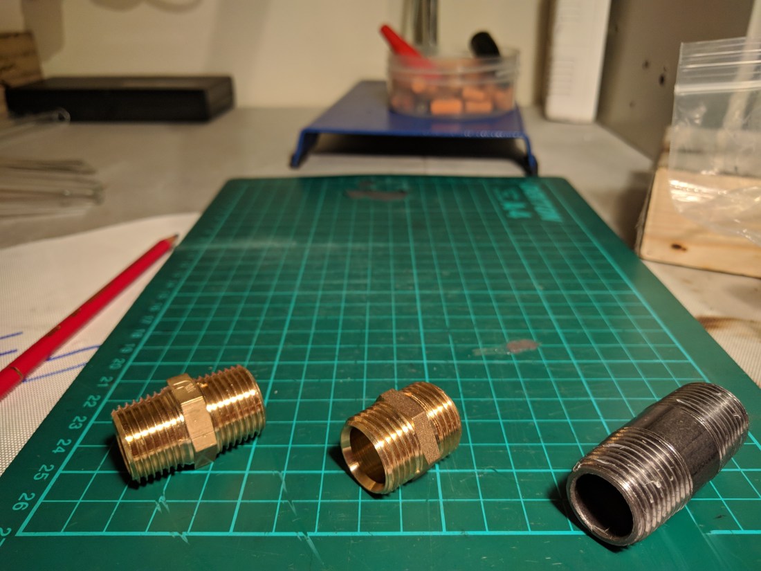
Standard nipple lengths are typically in the 1″ – 3″ range, with the maximum common size depending on the pipe diameter. Longer lengths are available although these are often special order items and are known as extended barrel nipples. Long fittings are useful when a pipe needs to pass through a wall, or where the air source is at some distance from the point where it will be used.
Flexible hoses or ducts may be used to connect between pipe sections where extra flexibility or reach is required but these add resistance to air or gas flow and should be kept to a minimum.
Equal Tees
An equal tee is just a three-way coupler with the three threaded fittings arranged like the strokes of a capital ‘T’. They are available with both male and female threads although all-female fittings are the most common type. Female equal tees can be assembled into a more complex arrangements using nipples and other fitting types.

Tees are commonly used to construct a manifold: a piece of pipework having an inlet and two or more outlets. Manifolds are used in both the fuel gas and air delivery systems in neon workshops to split the supply between various appliances.
A series of tees is often chained together using short nipples, with the inlet at the first tee piece and a blanking cap inserted in the final one: each tee in the series then provides a single outlet port through its “side” arm.

Four-way equal unions are also available which can be used to build a manifold with ports on both sides: depending on space and access requirements these fittings allow a shorter manifold body as long as hoses can be conveniently run to both sides of the fitting.
Hose barbs
Hose barbs, also known as hose tails or just tails, are the last fitting needed to build a useful air distribution system. They allow a flexible hose to be joined to a BSP fitting in a pressure tight fashion: the barb has a series of conical ridges designed to lodge into place in the hose wall, and a properly tightened hose clamp completes the seal.
Barbs are available with male or female BSP threads: tapered male connections should be used for fuel gas applications to ensure a gas-tight seal. Female fittings can be used for air manifolds and to make hose couplers, splitters, or reducers from multiple hose barbs and appropriate tees or nipples.
Barbs are available in a huge range of sizes. The most common industrial sizes are much too large for typical neon burner hoses. Practical sizes for our purposes are generally no more than 6-12mm, or 1/4″ – 1/2″. Flexible hoses for hand torches may use barbs as small as 5mm or 3/16″. It’s worth figuring out which sizes fit well with the hoses you plan to use and then bulk buying: spares are handy for future expansion and most sellers offer discounts for purchasing packs of 5, 10, or other multiples.

Valves
Although it’s possible to build a fuel gas manifold using only nipples, tees, and hose barbs, it’s often preferable to have a bit more control. My first two attempts at gas distribution (a hokey series of ‘Y’ and ‘T’ splitters and then a simple monobloc aluminium manifold) lacked this feature: it’s a pain whenever maintenance is required at one of the burners since you need to de-pressurize the whole system before undoing any hose. This wastes fuel and makes the shop smell bad.
There are three types of commonly available valve that are useful in neon air and fuel gas systems: the ball valve, the needle valve, and the gate valve.
Ball valves
Ball valves are the most common type of valve for fuel gas shut off applications. They consist of a straight-through pipe bore seat with a rotating “ball” having a matching bore machined through the centre. A lever attached to the ball allows it to rotate a quarter turn (90º), fully opening or closing the valve.
Although they can be used to adjust the flow between fully-open and fully-closed, it is normally recommended that they only be used in either one or the other position since the valve construction causes turbulent flow in part-open positions, and the control provided to the operator is extremely coarse. A ball valve is normally full bore: when fully open it imposes no restriction on the flow of the gas compared to the surrounding pipe.
Some older burners use this type of valve for controlling the gas flow. This makes for an exciting life.
Ball valves are available with a wide range of handle styles: two of the most common are the lever valve and the butterfly valve. Lever valves are often used as a master shut off, since they are easily operated and provide a clear visual indication of the valve status from a distance (the valve is always open when the lever is parallel to the pipe). Butterfly style handles are useful in manifolds since their compact size allows them to be placed side-by-side on adjacent equal tees with only short nipples separating them.

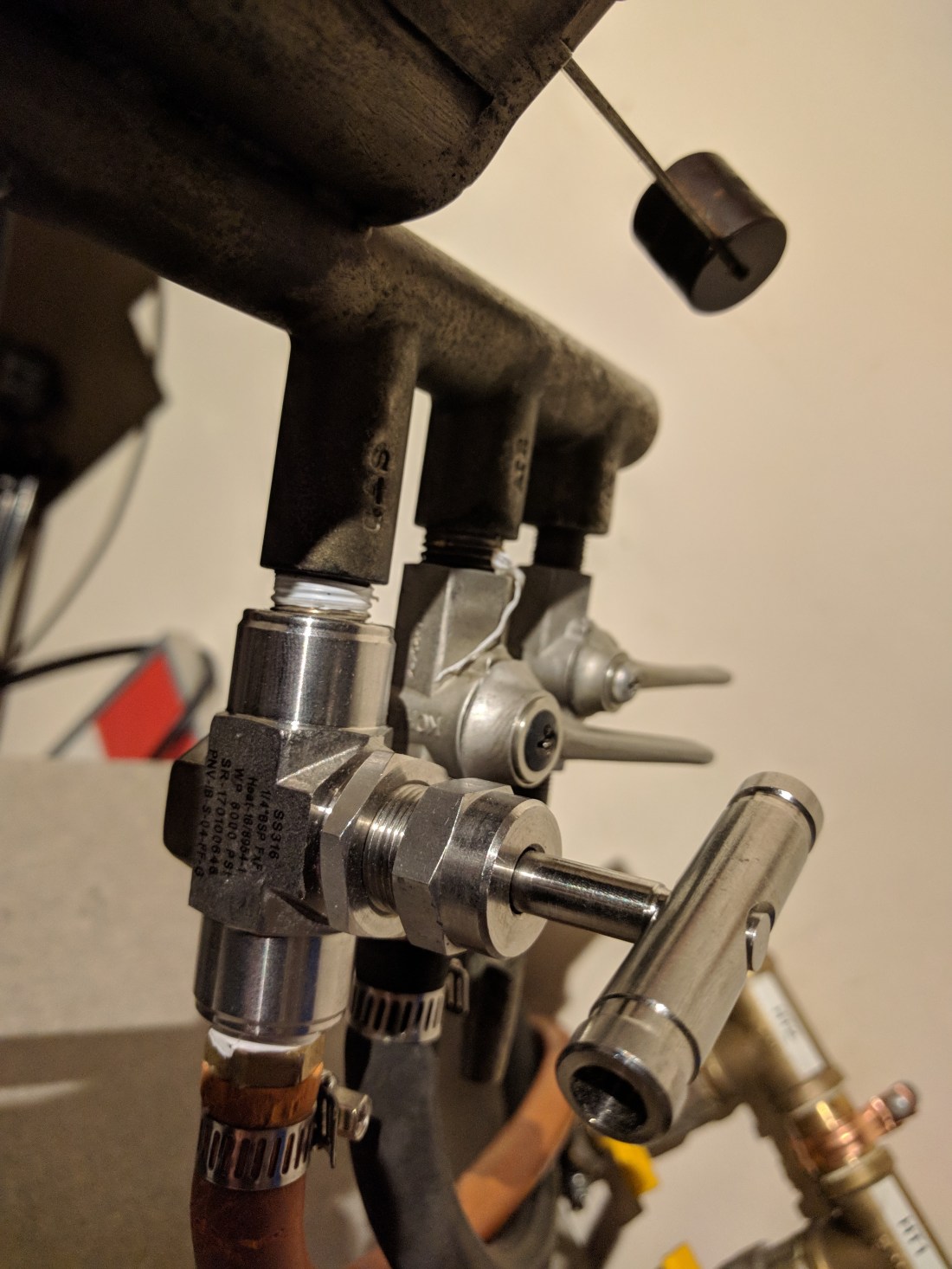
Needle valves
A needle valve has a small port in the inlet, and a threaded, needle shaped plunger which moves in and out of a seat in the port to close and open the valve respectively. Needle valves allow precise control of the flow and are commonly found on burners and torches for neon use (as well as in the gas delivery lines of the vacuum manifold). Because of the construction of the port a needle valve cannot be full bore: it will always impose some restriction on the flow and for this reason these valves are not usually used in shut off applications.
Gate valves
Gate valves are a simple type of valve similar to sluice gate: a baffle, or gate, mounted on a threaded rod slides in and out of a channel in the valve body to restrict or open the valve bore.
Gate valves are sometimes used to construct a simple relief, or blow-by, valve for the blower used to supply air to the torches: since the common side-channel blowers used for this application rely on the stream of air passing through the machine for cooling they can overheat if run with all the burner valves closed for an extended period.
A gate valve mounted in a tee piece connected between the blower and the air manifold allows for a small volume of air to escape and ensures a continuous supply of cool, fresh air to the machine.
Couplers & reducers
Couplers and reducers allow two male threads to be connected together, or allow a BSP thread of one size to be adapted to another thread size or gender. Like nipples, couplers are available in barrel and hex formats and allow two BSPT male threads to be connected together to make a gas-tight seal (for example, when connecting a male hose barb to a brass compression fitting at the intake of a fuel manifold). Reducers are available in a wide range of pairings to allow almost any combination of threads to be used together.


Sealing the deal
Since the air supply needed for neon use is relatively low-pressure (only around twice atmospheric pressure but at relatively high flow rates) sealing is less critical in components carrying air to the torches. Regular PTFE tape or simple rubber washers provide an adequate seal and are easy to maintain or replace. Air also has the upside of not bursting into flames when it escapes unexpectedly.
For fuel gas use the situation is a bit different: although the manifold is never exposed to the high pressures of the gas bottle (it is always installed after the regulator and handles a pressure of at most 4 bar for a typical adjustable propane regulator), it is still high enough that, when added to the flammable nature of the gas makes closer attention to thread selection and sealing a safety critical matter.
There are three main methods of achieving pressure tight seals in threaded pipe:
- Jointing threads: long, tapered threads that mate tightly to create a seal.
- PTFE thread sealing tape
- Jointing compound
Jointing threads can be used alone when sufficiently long threads are available on the required fittings, and when the final orientation of the fitting is unimportant: since they must be tightened to a certain point to achieve a tight seal it may be impossible to achieve a particular desired alignment between fittings.
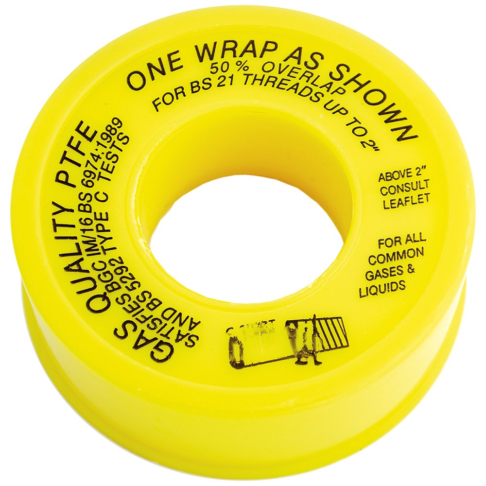
PTFE thread sealing tape is available to meet a range of standards. For fuel gas applications tape conforming to BS6974 should be used. It’s sold as “gas PTFE tape” or “gas grade” and usually comes in a yellow reel. It’s thicker than the normal PTFE tape and should be applied according to the packet instructions (normally a few turns with partial overlap between turns).
Jointing compounds are pastes, gells or fluids that are applied to the thread to create a fill between the two mating threads. They come in two forms: drying, and non-drying.


Drying jointing compounds are similar to thread locking compound: essentially they are an adhesive that bonds to the thread material and creates a gas-tight seal down the length of the thread. Both rigid and flexible formulations are available: the flexible versions contain PTFE, silicone or rubbers to create a vibration tolerant seal. Drying compounds need to cure for around 24 hours before use and must be thoroughly cleaned, re-applied and re-cured when disassembled for maintenance: check the bottle label for specific instructions. Cleaning may require the use of solvents or abrasives (wire brush).
Non-drying compounds are thick, oily pastes that create a gooey, viscous seal between moving thread components. They are applied in excess (until the threads are no longer visible), and then wiped from the finished assembly. They are messy as all hell, a bit smelly, and kinda crude, but they have the great advantage that they allow parts to make small movements while maintaining the seal, even after final assembly and installation. This allows manifold components to be freely assembled to a desired alignment, and permits final tweaks and adjustments to be made at a later time.
Non-drying formulations also have the advantage that they can be easily removed with rags and soapy water if for any reason a joint needs to be re-made or changed to a different kind of jointing compound.
Tooled up
You don’t need a great deal in the way of tools to work with standard pipe fittings for air applications: most connections can simply be done up hand tight. Main connections and the connections to the relief valve can be tightened with a pipe wrench or vice grips.
For fuel gas, connections need to be tighter and better tools are needed. A 4″ or 6″ bench vice is useful for assembly: wrap fittings in rags, or cover the face of the jaws with cardboard to avoid scratches.
Spanners or sockets to suit the fittings being used are essential to properly tighten components. Ratchet spanners and deep sockets can be used to turn fittings like hose tails, cutting down on effort.
Butterfly valves can be tightened in a couple of ways: by gripping the valve stem around the body with a pair of mole grips, or by tightening an adjoining hex fitting (usually the hose barb fitted in the valve outlet). Care is needed to avoid damaging the soft valve body. It’s best to avoid using spanners on these valves: although they fit and will turn, the body is octagonal and will slip easily in a ring or open spanner.
Lever valves normally have an exposed hexagonal section that can be tightened with an open spanner.
When disassembling parts that have been wrapped in PTFE tape, a wire brush comes in handy for quickly removing the tape and cleaning up the threads. Brush along the threads and then pull the tape away as it unravels.
Air main and distributor
I use a Greenco side-channel blower to provide air to the burners in my workshop. Because it’s a large and heavy machine it’s mounted next door in the garage. A remote start/stop switch allows it to be turned on without leaving the shop and the air main passes through the drywall to the back of the workshop.

The blower has a 1-1/2″ BSP(F) outlet and this passes through a BSP coupler (to allow the blower to be easily removed for maintenance), and into a 1-1/2″ equal tee. In the side port of the tee a BSP gate valve is mounted to provide the necessary relief valve. A simple in-line silencer fitted after the valve helps to reduce noise from the escaping air.
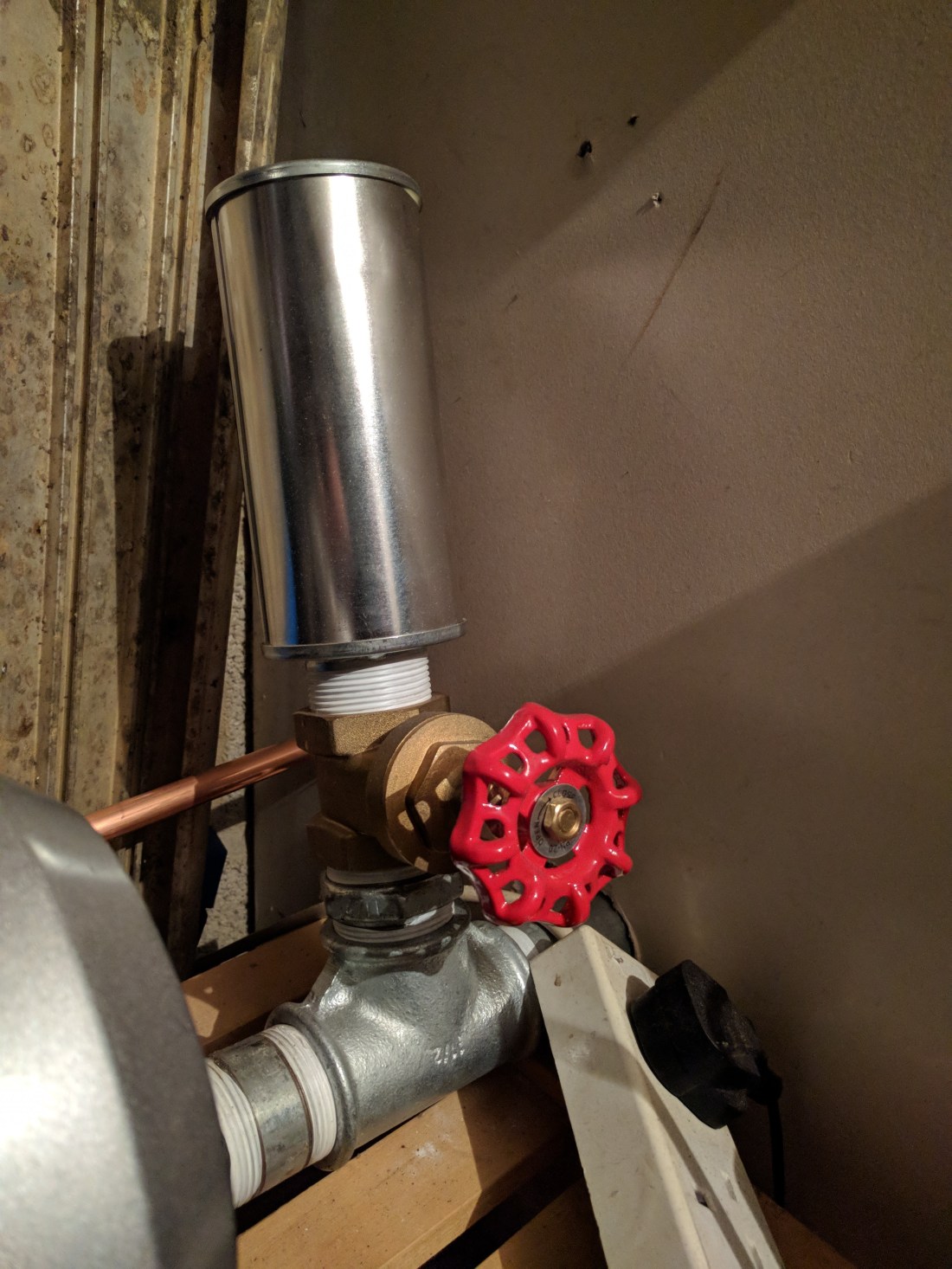
This arrangement was supplied with the blower: to be honest, it’s not ideal. It’s noisy and inefficient. A better solution would use a spring operated pressure relief valve of some kind to only open the channel when needed but since it’s out of earshot, and since I tend to only use one burner at a time, it hasn’t been a high priority so far.
The air main comes into the workshop a little over the height of one of the benches, and takes an immediate 90º turn down through a hole in the bench top. Ideally, the blower would have been mounted lower down but this was not possible due to an existing workbench and shelves in the garage. In the end it’s not a big loss since the area of bench affected is “dead” anyway: it’s at the back and out of comfortable working reach.
Beneath the bench the air main splits into a manifold to supply air to each individual burner via hoses. The two largest “air loads” (the two ribbon burners) are attached directly to the 1-1/2″ air main via reducers and barbs, and the remaining burners are supplied from a series of three 1/2″ equal tees with 6mm BSP barbs.


All the joints are sealed with standard grade white PTFE tape, and the hose connections are clamped with good quality hose clips.
Hitting the gas
For fuel gas, I started out with a single supply hose to one burner (a Nortel Minor gas/oxygen bench burner). As I added burners I used tee-pieces and ‘Y’ splitters to build a terrifying labyrinth of gas hose. Even though I checked every connection every morning the set up made me nervous and was ugly and unreliable.
If you are using splitters it’s best to use the brass ones: plastic parts are prone to deforming when the hose clamp is tightened and may start to leak after they have been installed.
After a short while I upgraded to a simple manifold: an aluminium monobloc body with five 1/4″ BSP(F) ports.
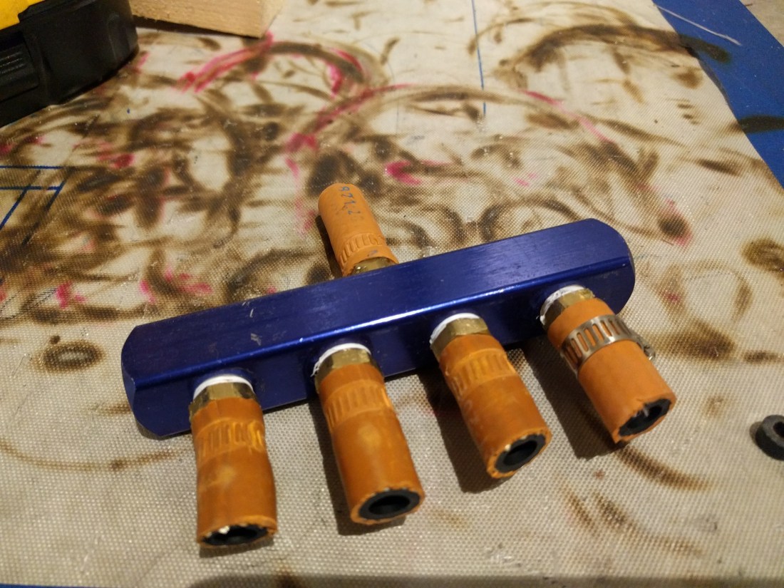
This allowed me to hook up up to four burners simultaneously. A pity then that I had five (requiring a splitter still to run both hand torches). I was never very happy with this manifold: they are designed for use in caravans and motorhomes but the threads are very shallow and poorly cut, and being aluminium, prone to damage and wear. Even with as much PTFE tape as you can cram in it is hard to get a satisfying seal and the right hand port always had a minute leak. Other caravan manifolds are available with integrated valves but these use compression fittings to copper pipe and are less convenient to use with standard BSP fittings.
A few months later I decided to put something better together.
The new manifold is constructed from 1/2″ brass BSP fittings, with a main shut off lever valve and a separate butterfly valve for each burner. The body of the manifold is a series of six female equal tees, joined together by 2″ nipples and with a blanking plug in the end port of the final tee. The manifold inlet is a brass 1/2″ BSPT(M) to 15mm compression fitting: this accepts a copper pipe which is run in through the garage (adjacent to the air main – the pipe is just visible at the left of the photo of the blower above). This means I no longer need to keep the front door open for the gas hose to come in: since it’s winter now this is easily the biggest win of the whole project.


Once the manifold was assembled, using Slic-tite to seal each thread, the manifold was tested for leaks outdoors. Once everything was tight to the point that no leaks could be heard a soapy water solution was used to find remaining leaks.
For each leak the affected thread has to be tediously disassembled, cleaned, replaced if necessary (it’s easy to knock the smaller brass nipples off-round by overtightening them, I learned), and then re-tested but eventually I was able to get something that seemed to pass muster.
It was installed onto the workshop wall using rawl plugs and copper saddle clamps, with spacers made from short sections of 13A electrical cable insulation.

Apart from a couple of compression fittings that needed minor tightening a few weeks after it was put in, both manifolds have worked great: they get the gas and air where they need to be and keep the hoses as tidy and out of the way as possible.
