My benches are based on the standardised work tables developed by the US Experimental Aircraft Association. These are a set of plans for small, modular tables that can be clamped together to create larger units for assembling aircraft wings and fuselages.

The plans are easy to follow and can be built adequately for neon use by anyone with very basic word working skills: they are entirely made from sections of 2×4, doubled to add extra rigidity where required.
My benches use exactly the same scheme as the EAA plans but modified for my size requirements and to create spaces for various bits of the neon plant.
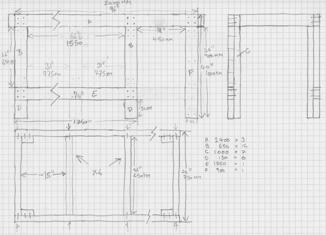
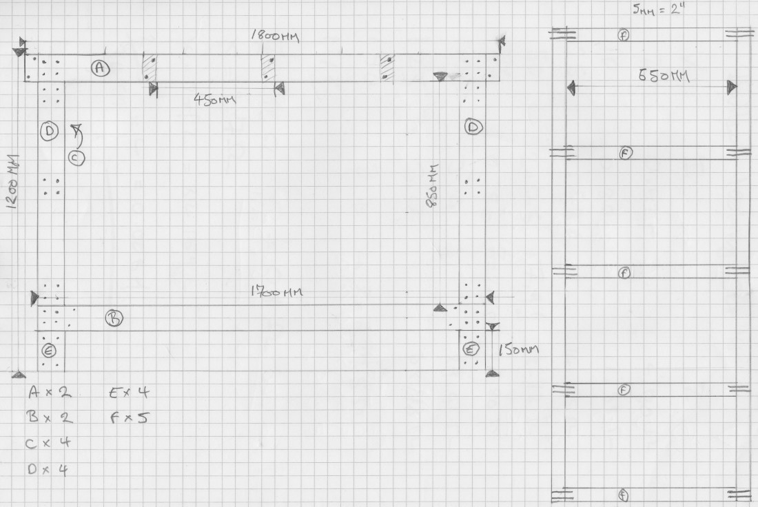
There are just five separate cuts (and a few hundred woodscrews!). I used a Fisch countersinking chuck from Axminster Tools: it’s a great timesaver that avoids having to swap bits all the time.
Processing bench
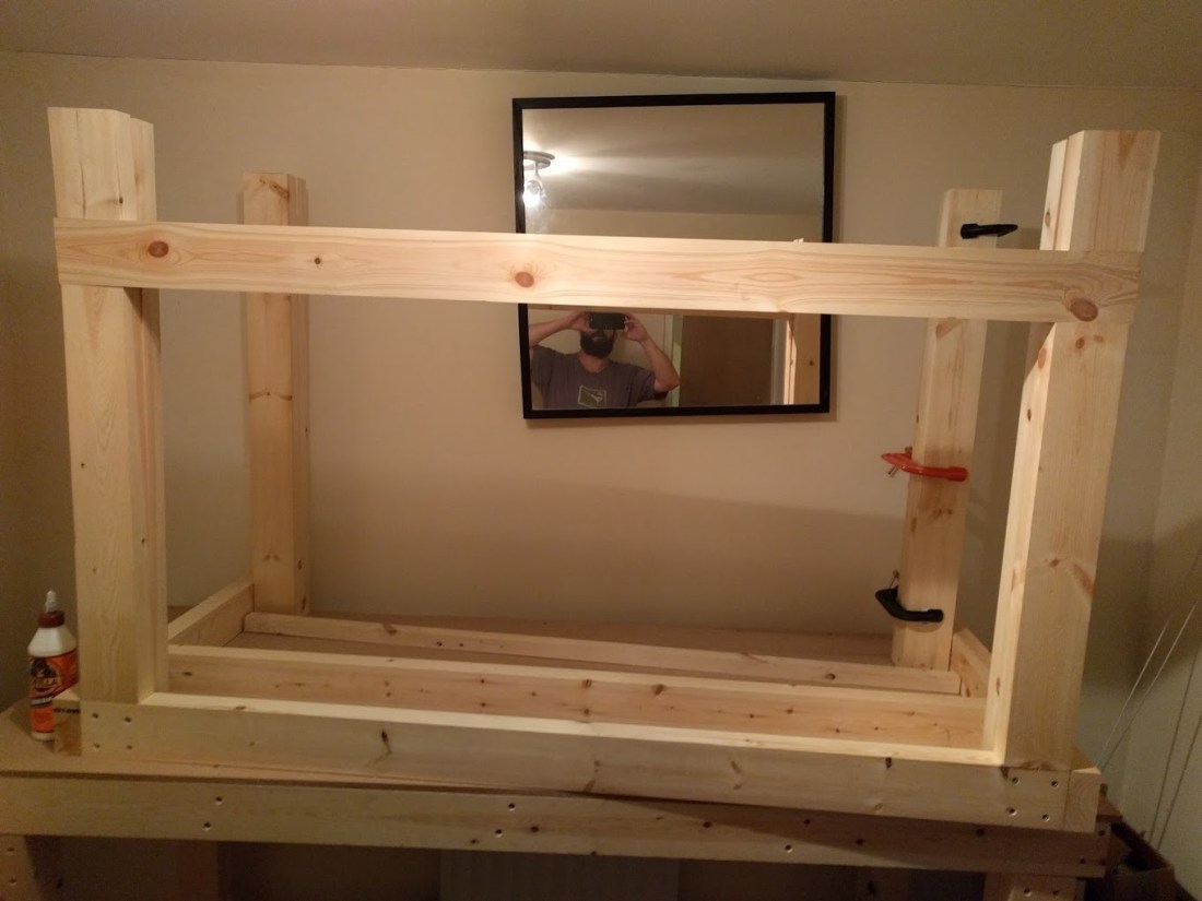
My first design for the processing bench called for six legs, and a gap at the right hand side for the bombarding transformer to sit in. In the end, I decided to put the transformer at the other end of the bench, in the empty void between the pattern bench and the processing bench, so I switched back to a simple four-legged design.
This was built in-place over a couple of days last year. The build was generally smooth and pretty straightforward: the most difficult aspect of building it by myself was manoeuvring the assembled bench into position, and arranging jigs and supports to take the weight of the pieces as I put them together.

To cut the timber I used a Makita mitre saw: probably overkill for this project since it’s entirely made up of straight cuts, but with the added support of the stand it makes for very quick and efficient cutting.


Each individual “unit” of the bench (each leg, the ladder) is screwed and glued with white wood glue. The final assembly only uses screws so that (in theory!) the whole thing can be taken down and moved.
Pattern bench
For the pattern bench I needed to make further changes to the EAA designs: since this bench has all my drawer cabinets underneath it it needed to have enough clearance beneath the work top to allow this.
The original supports and top for this bench started life as an IKEA table that I had in my student digs in London about 18 years ago. Since then they’ve been a desk, a TV stand and most recently an electronics workbench.
Although the 1″ pine top was still pretty solid, the IKEA trestles were not going to provide enough stability for use as a neon bench: it was time to build new legs and a frame.
Instead of the ladder construction of the processing bench, there are two 2x4s, roughly 8″ apart bracing the rear of the bench (the cable channel to the control cabinet passes down between these), and the rest of the legs and support frame are constructed exactly as in the EAA design, but without the upper and lower horizontal 2x4s at the front.
The leg heights were carefully measured and cut to ensure that the table top rests on both the wooden frame and the top of the metal cabinets, providing additional stability and reducing wobbles.
Final installation
Both benches were eventually wrestled into their final resting places before the tops were cladded with 12mm tilebacker board. This is a heavy, cement based composite board that is heat resistant and reasonably cheap and easily available.
The only downside is cutting it: it eats jigsaw blades for breakfast, while laughing maniacally and spitting out bits of hardened steel. You can cut it with a hand saw but expect to dull the blade within a small number of cuts.
It’s also a great way to stay in shape!
When the choke was ready for installation an additional two legs were added to the processing bench, following the existing template, in order to provide additional support to the shelf for the 50KG choke windings and 15KG core.

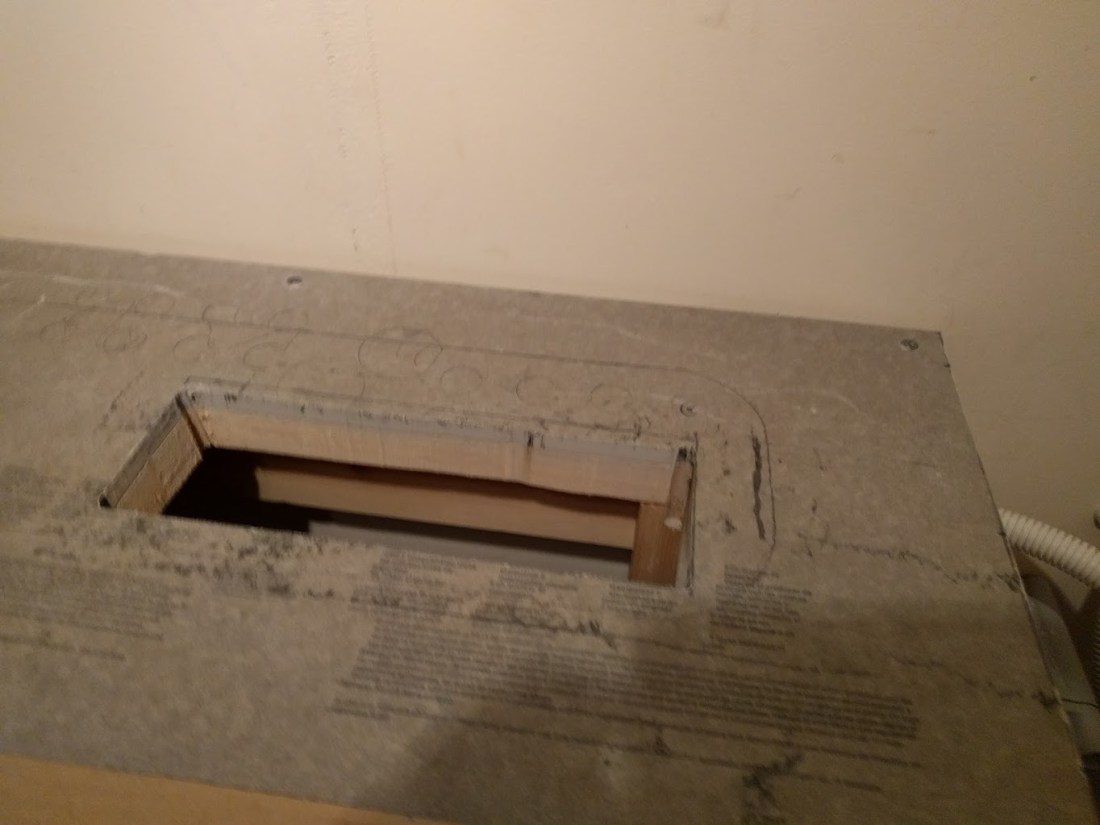
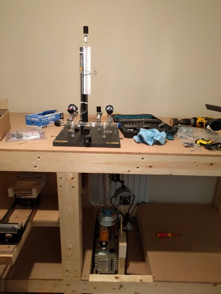
A final modification was made to the processing bench to install the pumping equipment: a section of the lower shelf was cut out to make a slot, allowing the mechanical pump to sit on its own isolated platform, reducing the transmission of vibrations to the rest of the pumping equipment. This also makes it possible to get a shallow pan in underneath the vacuum oil drain in order to change the pump oil.
This is one of the great features of the EAA designs: even though they are not the most sophisticated construction in town, and although they are quite heavy and bulky, they are easy to modify and extend: even after they have been installed.
In the future I plan to swap the pumps and choke around to create more space on the pumping bench: although it’s a big job that I’m not really looking forward to the change to the benches should be quite simple.


