Right then, welcome back to the third, and hopefully final part of this exciting exploration of the wild world of ballasts for neon bombarding. In this post I’ll go through the final choke build, testing, and installation and take a look at how the finished choke performs in actual use.
If you missed the first two parts you can find them at Ballast to basics and All choked up.

If you made it this far, well done! It’s a pretty dense topic and it certainly isn’t going to interest everyone but if like me, you are in a position where you need to cobble your own choke together, there’s hopefully some useful information to get started from here.
The previous owner of my bombarding transformer unfortunately disposed of the choke that was originally used with it: if you can find one for sale, I’d certainly recommend investing in a commercial choke. As with bombarding transformers there are numerous benefits to a well-engineered device built with neon processing in mind.
Sadly they don’t appear for general sale very often: I’ve been looking in the UK for several years (first for Tesla coil use, then neon) and I’ve yet to come across one. If you’re able to invest in new equipment then there are numerous options available including modern saturable reactor designs that are both smaller and easier to control than the traditional mechanical choke.
Choked on its own bobbin
As we found out in the last article, the first prototype didn’t really cut it as a choke for our purposes. The maximum inductance of 11.18mH just doesn’t produce enough impedance for the application.
Two parameters that have a large influence on the maximum inductance in this case are the turn count and the core window or aperture. The turn count is just the number of turns making up the winding and the core window is the cross sectional area of the opening through which the core passes. This in turn limits the core cross sectional area (which must be small enough to slide in and out of the window) which limits the extent to which the presence of the iron core is able to increase the coil’s inductance.
Since the first attempt wasn’t that far out of the ballpark I decided to stick with the original strategy and just increase some of the parameters of the original build. Fortunately there’s a larger version of the flat channel duct available from the same supplier: 150mm x 70mm rather than 110mm x 55mm. This increases the core window from 6050mm² to 10500mm²: a factor 1.74 increase.

As well as increasing the CSA I decided to increase the turn count: unfortunately, increasing CSA for the same length of winding reduces the turn count due to the longer path around the winding form. Thanks geometry. To increase the turn count by 50% to 300 turns on the new form, and using the same cable as previously, requires 230M of 16mm² welding wire rather than the 100M used in the first build. This is the main expense in building the choke.
Wind it up
A new winding engine (if it’s fair to call anything assembled from lumps of 2×4, box section and nails an ‘engine’) was hastily assembled and put to work winding on the cable. The first 100M was taken from a new drum and then the windings from the previous attempt were recycled. The last 30M came from an offcut from a previous project (installing a winch on my Land Rover).
One property this engine shared with its predecessor was a tendency to self-destruct toward the end of the winding process: with hindsight, the 3/8″ threaded rod stock I used for the main axle was never going to be very happy supporting the weight of 230M of cable (about 50KG at today’s prices).
Even so, the contraption held it together at least until the final turn could be secured in place, and the monstrous beast of a coil was wrestled from the remains. It’s not something you want to be moving around alone, I soon learned.
With the winding complete it was time to shift back to the big bench and get the testing started. As before the first test is a simple inductance reading for the coil.


The first measurement was made with the coil still on the winding frame: although technically the axle of the frame counts as a kind of core, it’s small enough to ignore for practical purposes. This first reading was 7.18mH without a core: this is in the same range as some of the measurements from the first prototype with a core inserted. It’s still low enough to produce a current in excess of 70A into a short circuit, but it’s approaching the range that’s needed.
The second measurement is shown with the coil standing on end and a simple test core of uncut welding rods inserted into the upper window. The rods are packed tightly in individually wrapped and insulated bundles to limit eddy losses. This time the inductance reading is 28.3mH, almost three times the original!
With further improvements to the core packing it was possible to raise the maximum impedance to just over 33mH.
Let’s run that through the impedance and current calculations and see how it holds up for our purposes.


Just twenty seven amps! Progress! Although this is still a little on the high side, it’s a big improvement: the bottom end is not as low as we’d like but more importantly the range is quite usable. If we repeat the calculation for the lowest inductance we come out with an impedance of 2.26Ω and a current of 106A. That’s a range of 6.63Ω and almost 80A.
At this point, I could either extend the current coil, or wind a new one and start again. Because of the dimensions of the original, adding more layers consumes additional cable at a progressive rate as well as making the choke heavier and more cumbersome. Moving to a new design to overcome some of these limits would likely mean switching to a new form and using single core enamel wire to reduce the size of the windings.
Stick shift
Before doing all that I decided to try adding some gears to my prototype slide choke. Instead of making a new coil to try to hit the sweet spot of the inductance range, I’d build a “pre-ballast”: a fixed inductor that can be placed in series with the choke to add further impedance in the line.
After poking my inductance meter into a bunch of assorted transformers, chokes and other wound objects in the workshop I didn’t find anything in the kind of range needed that would work.
If we work backwards from the desired current ranges to the inductance that will provide the corresponding impedance we can work out what we’re aiming for.
For example, to allow a minimum of 10A and a maximum of 80A for a transformer having a minimum (closed circuit) impedance of 0.52Ω we can calculate the minimum and maximum impedance as:


Where 


Plugging in our desired current values:


And obtaining the required minimum and maximum inductance (


So the ideal range for our current requirements spans from 7.89mH up to 74.7mH. The current coil is pretty close for the bottom end of that range but it only extends a little under half way toward the desired maximum inductance.
Around this time I (literally) stumbled over a 5KVA 110V tool transformer that some idiot had left lying in the middle of the floor. If you’re not familiar with these quaint British contraptions I’ll give a quick explanation: these are centre-tapped earth (CTE) transformers designed to provide additional safety when using power tools, especially on construction sites. The main point is that, because the centre of the secondary winding is referenced to earth you have two 55V “live” conductors instead of a 110V live and a ground-referenced neutral: this cuts the phase-to-earth voltage down to something generally accepted as safe and reduces the shock hazard when coming in contact with a single line.
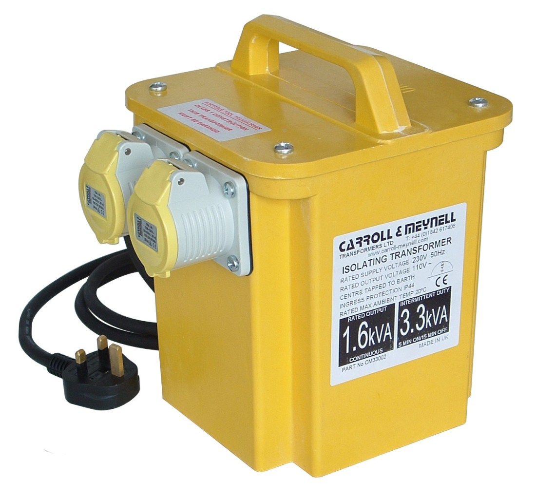
All of that’s great, but for our purposes it’s just a really big, chunky inductor in a box, sitting their waiting to begin a new life… Out of curiousity more than anything I stuck the meter probes first across the primary (not very useful), and then across the secondary windings. The secondary came up at around 40mH and is wound in heavy gauge cable rated for at least 40A (and even then conservatively). Even better: with the primary winding shorted, the inductance drops to around 8mH giving a usable “second gear”.
Added to the inductance of the choke itself, and the small amount of impedance provided by the transformer these fixed inductances allow the sliding scale of the choke to be used over the entire range of the bombarding transformer. The major disadvantage of this arrangement is the need to “change gears”; to switch out one fixed inductance and switch in another (or to bypass the pre-ballast entirely).
The transformer was quickly gutted of its former attachments, and given a brand new interior:

A little scrap of DIN rail was hotglued into the transformer housing, to seat a pair of terminal blocks for the ballast send and return feeds and internal wiring, and a small contactor to open and close the primary circuit allowing the two levels of ballast to be selected remotely. The ballast loop and control wiring are then routed back up to the control cabinet via a 100A bypass switch to allow operation of the bombarder without the fixed ballast in-circuit (third gear!).
To test this set up a similar rig to the one used in the previous post for prototype #1 was assembled, with the bombarding transformer attached as the dummy load.

The test voltage can be varied or set to a fixed value using the variac, and the current is monitored in both the high- and low- voltage circuits. Additionally, the digital meters at the front can measure the power factor and real and apparent power. To test the behaviour at line voltage the variac can be taken out-of-circuit and the ballast is attached directly to the line (as shown in the photograph).
By fixing the voltage, and progressively withdrawing the core further out from the windings while recording current measurements it is possible to plot the core / current characteristics of the choke:


It should be noted that this is definitely not a use that the manufacturer supports: it’s a bit of a hack, and, while safe, is not something anyone should attempt unless they are comfortable risk assessing projects involving mains electricity, and have an understanding of the limits and parameters of the equipment involved.
For reasons that are hopefully obvious the control for the ballast switch is routed to a toggle switch on the front panel labelled magic and more magic.
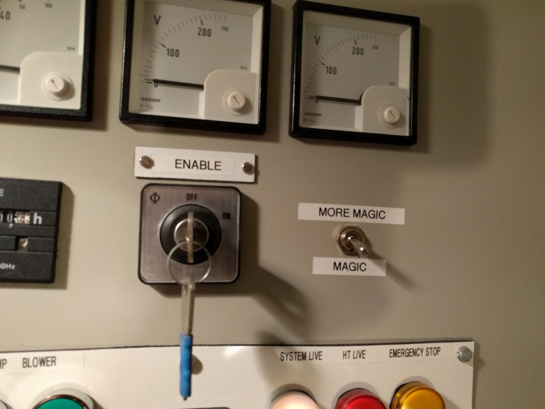
More seriously: it’s hard to put accurate values on the switch, since the actual ranges depend both on the voltage setting of the transformer, and to a lesser extent, the characteristics of the load. When the switch is in the “magic” position the lower current range is selected, and when the switch is moved to the “more magic” position the higher current range is used. For this reason it’s really just a “high” / “low” switch (but I prefer magic and more magic).
Plywood and diesel power
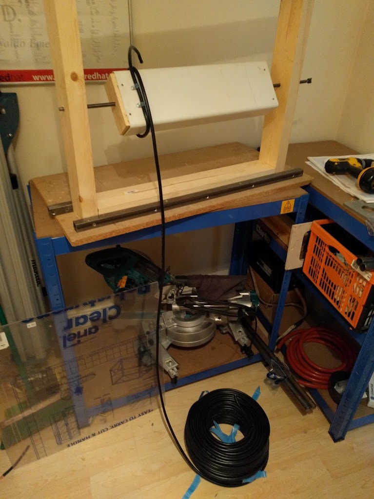
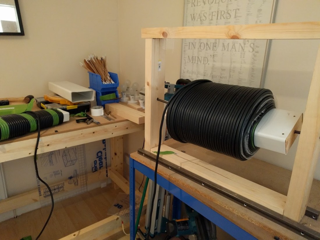
With usable ranges working the final step was to install the choke into the processing bench, and to build a mechanism for the core to slide in and out easily. To do this, plywood end plates and a supporting shelf of MDF for the choke winding were cut with a jigsaw and installed into the existing framework of the bench with the front of the coil form emerging from the front window.

To allow the heavy iron core to easily move in and out the control rods were re-packed into a shell made from two sections of duct trimmed down to allow them to fit snugly inside the ducting making up the coil form. Plywood end caps are fixed into the end of the shell sections to help add rigidity and to keep the rods in place. A simple handle made from dowel is attached to the front end cap to allow the core to be manipulated.
When the choke is at its maximum power level the core is completely withdrawn from the wound section and the 15KG weight of the core must be supported. A roller fairlead from a Land Rover winch was repurposed for this task. After removing the two long (normally horizontal) rollers, and grinding down the supports on the two remaining rollers to make clearance for the core, a suitable support was created.


Compared to commercial models it’s certainly clunky, and takes a bit of dexterity (not to mention muscle power) to use effectively, but as a first attempt it certainly works: since I first got the bombarding equipment working in March I’ve processed around forty or fifty units with very few failures.
All the bad tubes have been down to either my glass working skills or problems in the vacuum system I’d failed to spot.
The biggest annoyance is still the need to change gears: for both small and large electrodes (low power 10mm and high current 12mm and 15mm) it’s not an issue since the entire bombarding process uses one or the other of the two ranges.
Typically, it’s the electrode I use most often (30mA and 45mA 12mm) that span the “magic” and “more magic” ranges. These need to start off at 150mA or 200mA (low to mid way through magic), and progress up to around 500mA (mid range of more magic). There’s an awkward bump as you have to power off, switch range, relocate the core, and then power back on. It’s annoying and a distraction but it doesn’t seem to affect the finished tubes.
If you’re using a pre-heat cycle (heat at low current to 100-200°C then evacuate for 30s to remove primarily water vapour) it’s sometimes possible to jiggle the current settings around a bit so that the range switch happens during the pre-heat evacuation: this makes the whole operation much more smooth and less of a hassle.
I’m still on the lookout for a commercial choke that I could swap into my set up, but before that happens I may still come back to the choke and try a new build using enamelled wire and a different form. With the experience I gained from building these two I think I could come up with something smaller and without the need for any fixed pre-ballast to adjust the range.
And with that we come to the end of our exploration of homebrew neon bombarding chokes. Thanks for taking the time to read through the articles and please use the comments or contact section if you have any questions or feedback.
I’ll leave you with some final photographs of the choke in action: processing “Unit #1“: my very first piece of neon to survive bending, electrode welding, bombarding, filling and tipping off using my own equipment.
Don’t get too excited: it’s a two foot straight stick filled with argon! It actually began life as a two-and-a-half-foot stick, but the first few attempts at electrodes didn’t go so well… There’s also a shot of “Unit #0“: a U-shaped curve that sadly did not survive tipping off.


(the eagle-eyed reader will notice that Unit #1 is actually being aged, not bombarded: I think after the debacle of Unit #0, where I completely lost the plot after the bombarding worked, I decided to put the camera down and focus on what I was doing).
