After getting hold of a usable bombarding transformer the next step was to try to buy or build the necessary controls to allow it to be used to successfully process tubing. In this post I’ll discuss some of the theoretical background involved in designing high power ballasts: next time I’ll go through the design, prototyping and build of the choke to control my bombarder.
The electrical controls for a neon bombarder are actually quite simple: one or more on / off switches to control the low voltage supply to the transformer and a current limiting device to allow the current to be varied over a range of levels. Ideally the current control should allow the current to be adjusted smoothly over a wide range: from one hundred milliamps or less to currents exceeding one amp.

In electrical engineering terms the goal is to construct a variable constant current source: for any combination of voltage or current setting the source delivers a near-constant current into a load that appears as a near short circuit.
The open circuit voltage in this arrangement is high, but sags once the arc has been ignited, and the bombarder continues to provide a uniform, constant current flow for any given setting.
This behaviour is needed since the discharge in the tubing has a property known as negative resistance (more properly a negative differential resistance: 
From the power supply’s point of view this looks a lot like a short circuit: the constant current source is needed to restrain the current in the arc and prevent the power rising to damaging levels (a constant voltage source would keep delivering more current until either it ran out of amps, overheated, blew a fuse, or the tube failed).
Electrical ballasts: 101
Current limiting devices are variously referred to as ballasts, chokes, line reactors, and numerous other names depending on the exact application. The term choke is often (although not always) used to describe a variable current limiting device and is one of the most common terms for the devices used in neon applications. By analogy to the choke of an internal combustion engine, the electrical device allows the flow of current to be choked to a certain level.
A ballast is placed in line with the load requiring current limiting and typically imposes an impedance in the circuit: a resistance, reactance, or a combination of the two (actually in real world devices, it’s always a combination of the two but it is useful to distinguish between resistive ballasting and reactive ballasting for practical purposes).
Some types of modern electronic or magnetoelectric ballasts (for example saturable reactors) use different physical mechanisms to achieve current limiting: active electronics such as SCRs and switch mode power supplies, or altering the saturation behaviour of an iron-cored inductor. These newer and more complex ballast types are not considered further in this article.
Resistive ballasting
There are several ways to control the current flowing in a circuit. The simplest is to use a fixed or variable resistance in series with the load. This is the same basic idea as using a ballast resistor to limit the current flowing through a simple LED.
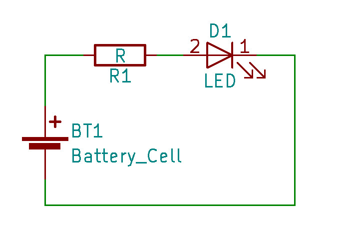
Consider the simple circuit above. A basic LED might have a forward voltage drop (usually written 

Rearranging in terms of 

The LED’s forward voltage drop is subtracted from the supply voltage to obtain the correct ballast value. Plugging in the values for 


This simple approach is adequate for small, low powered devices but it has a major limitation: the excess power (caused by the excess supply voltage above the device’s rated

This is the same phenomena sometimes referred to as “I-squared-R losses” in anything from power transmission lines to resistive losses in motor and transformer windings. For our simple example this works out as:

Not too bad in this case: the resistor can easily dissipate this heat in normal operating conditions and a more complex solution may be unnecessary. For simple low-power circuits the arrangement can be made more efficient by adding active devices to regulate the supply voltage.
If the difference between the supply voltage and the voltage drop in the device is larger a greater quantity of heat will be generated. If we wanted to run our LED from a 12V supply instead of 3V the numbers change as follows:


For an additional 9V drop in the ballast the ballast losses have increased to a quarter watt: this is much more significant, especially for small, low-powered devices.
If we consider the resistive case for a typical neon bombarding application it quickly becomes apparent that the technique has serious practical limitations for our purposes.
In AC circuits, as well as the simple DC resistance there is a second component to the overall impedance of the circuit arising from the interaction of alternating current with inductive and capacitative elements in the circuit. The normal DC component is termed resistance, while the remaining component is termed the reactance of the circuit. Together these values sum linearly to give the overall impedance in ohms:

A typical bombarding transformer may have a resistance of less than one ohm across the primary winding. Since it must be driven by an AC power source, and since the windings have the property of self-inductance we should also consider the AC impedance of the circuit.
The inductance of a transformer (viewed from the primary windings) will vary depending on the load: the maximum inductance is seen with an open circuit secondary, and the minimum when the secondary is delivering current into a short circuit.
For my bombarder the maximum inductance is 38.6mH and the minimum is 0.85mH. Using the formula 


The DC resistance of the primary, measured with a multimeter, is approximately 0.25Ω: adding this to the reactive component we find a total impedance of roughly 0.5 – 1.75Ω. It’s clear that if we apply mains power to this circuit with no ballast in line that the primary current will grossly exceed the rated capacity of the transformer:


This is a big transformer, but it’s not that big! At 20KVA the maximum primary line current is up to 100A (depending on exact line voltage): yet without ballasting we know that even with the secondary completely disconnected and passing no current we would draw over 133% of the devices rated current. With a typical neon load in circuit the line current would be almost five times the rated value.
It’s just as easy to calculate a resistive ballast for the bombarder as it is for an LED: we just need to pick a power level, plumb in the values for the transformer and current, and then solve for the ballast impedance. Since it’s a resistive ballast the 
We’ll work it through for the full power load since this is the “worst case” in terms of ballast losses and heat dissipation.


We know from an earlier step that the transformer’s own minimum (closed circuit) impedance is 0.52Ω (0.25Ω resistance and 0.27Ω reactance): so we need our ballast to make up the total to as close to 2.88Ω as possible:

Given that our ballast is in series, it’s also passing the same 83.33A as the primary: putting this back into the 

That’s over 16KW of thermal dissipation when running at full load! And since this is a resistive ballast, those are real, actual power watts that must be converted into heat.
Not only is this grossly impractical in terms of heat output, but we are throwing away enormous quantities of power just to restrain the current flow. At best the system approaches 50% efficiency: for every watt delivered to the unit being processed, another watt is spent heating up cables and the surrounding space.
People have built resistive ballasts of this nature and they are even used in some specific industrial applications (e.g. liquid resistance starters for very large induction motors: these are switched in during starting and prevent the enormous inrush current from destroying the motor windings, transformers or electrical connections).
Options for smaller scale use include switched arrays of toasters, electric fire elements, or large water butts filled with a salt solution and having either adjustable electrodes or a means to vary the salt concentration for adjustment. One benefit of using a liquid medium is that it provides a large heatsink for the considerable amounts of heat generated when in use.
Although people have built systems of this type and even used them for neon applications I decided pretty quickly that I wanted something a bit more sophisticated and with less frightening failure modes (Seriously: what could go wrong with having barrels of saltwater lying around a room that’s dedicated to high voltage work??).

OK, I should probably leave it here for now before everyone dies of boredom or 

4 thoughts on “Ballast to basics”