OK so welcome back to part two of the series on ballasting for neon bombarding systems. In this post we’ll take a look at the principals of inductive ballasting, and why it is a better bet for neon workshops than the resistive techniques we looked at in the last article.
If you missed part one you can read it at Ballast to basics.
Coils, cores and energy flows
An inductor is defined as a passive, two terminal electrical device that stores energy in a magnetic field when a current is passed through it. They are also referred to as coils, reactors, chokes and a host of other names, again depending on the precise application.
Inductors are frequently wound on a magnetic core made of iron, electrical steel, ferrite or some other ferromagnetic material. The core serves to confine and concentrate the magnetic circuit (field) and to allow greater power densities by permitting a smaller overall construction. The presence of a magnetic core will greatly increase the inductance of a given coil: in some cases the difference may be several orders of magnitude. In some applications the core may be specially modified or manipulated to provide additional control.
For example, conventional coil and core neon sign transformers have a gap, or shunt in the magnetic circuit (usually a small gap milled into one leg of the iron core) which serves to limit the current that can pass through the device for a given supply voltage: effectively a form of built-in magnetic ballasting. These types of current limited transformers are also known as leakage reactance transformers. This is in contrast to the bombarding transformer which has no in-built current limiting: given sufficient supply it will keep on delivering more current until it quite literally catches fire or melts.


For DC current an inductor is in most cases effectively invisible: the current will flow through the device opposed only by the resistance of the material used in the winding.
When an alternating (changing) current flows through an inductor it will interact with the winding’s magnetic field: the magnetic field surrounding the coil induces a second voltage across the windings.
Lenz’s law tells us that when this happens the direction, or polarity, of this induced voltage opposes the change in current being applied externally. In other words, the inductor stores energy: when the current through the device is increasing, the inductor can be said to be charging or energising: energy is being transferred from the electrical circuit into the magnetic circuit surrounding the inductor winding. When the current through the device is decreasing we say that the inductor is discharging: power is flowing out of the magnetic circuit and back into the electrical circuit. In this way energy is exchanged between the magnetic and electrical circuits: unlike the resistive case, where energy is simply radiated into the environment as heat.
For this reason inductors are often used to block AC interference from flowing in a circuit (for example, the little plastic/ferrite ‘beads’ found on some computer and audio visual power leads).
The capacity of an inductor is determined by its inductance, a value which expresses the ratio of the total magnetic field in a circuit (the magnetic flux, denoted by Φ) to the flow of current that sets it up (I). The unit of inductance is the henry (H) although practical inductors are more commonly in the μH and mH range.
A thorough analysis of inductance effects in AC circuits requires the use of Maxwell’s equations (or simplified derivations from them), and a consideration of complex impedances, voltage and current phase relationships and other esoteric and highly mathematical topics.
We’re not going to do that here (but I can recommend some great books if you’re interested!).
We know from the last article that for a given inductance, L, we will see an AC reactance for a given frequency, f, of:

Or equivalently:

And since we know that the frequency of the mains electricity supply in the UK is 50Hz we arrive at the expression:

Or equivalently, to find the inductance that will yield a particular reactance at the given frequency:

Electrical reactance is measured in Ohms for good reason: although it varies according to the frequency of the alternating current being passed, for a given frequency, it imposes an opposition to current flow of the same direction and magnitude as would an equivalent resistance, so a 10Ω resistor and an inductor having a 10Ω reactance at the supply frequency would pass identical currents when attached to the same supply (actually, this isn’t quite true since it assumes the inductor has zero resistance which can never be the case, but it’s good enough for our purposes).
Armed with these equations we can now determine inductance values for our ballast that will yield the desired current flows.
Variable inductors
There is just one minor problem with our discussion so far: all of our equations, as well as our models of practical physical inductors, consider only a single inductance value. We have already determined that for neon work we really want a mechanism that allows us to smoothly vary the current under the operator’s control: ideally, over the entire working range of the bombarder and other equipment.
A variable inductor is conceptually similar to a variable resistor and we will use it for a very similar purpose: smoothly varying the inductance value over a pre-determined range.
Variable resistors are commonly constructed with a track of resistive material and a movable wiper: as the wiper moves over the surface of the track the electrical circuit incorporates a greater or lesser extent of the resistive material and the electrical resistance increases or decreases accordingly.
An inductive component with a similar design is the variable autotransformer, or Variac™. This is a type of variable transformer that allows an input voltage to be stepped up or down according to the setting of a dial or lever. Unfortunately these devices are not generally suitable for current control in neon processing (although some modern ballast types do use them for control): a unit able to withstand the currents involved in operating at 20KVA would be prohibitively expensive, and it is not possible to control the voltage and current independently.
Historically fixed inductance coils with multiple “taps” have also been used for neon: these have the disadvantage of controlling power in discrete “steps” rather than as a smooth, continuously varying quantity.
The simplest type of variable inductor that meets all the requirements for neon work uses a fixed set of windings, usually of heavy gauge wire, and a movable iron core. When the core is fully withdrawn the ballast inductance is at its lowest, and current flow is at its greatest. As the core is re-inserted into the windings, the inductance increases smoothly with the core position until the core is fully inserted and the inductance reaches its maximum. This is the point at which the minimum current will flow: the circuit is fully choked.
The Slide Choke
By far the most common inductive ballasting arrangement for neon work, especially in the United States, is the slide choke. As the name suggests, this is a wound inductor with an iron core that slides in and out. Historically slide chokes were commonly mounted horizontally (or at a slight incline) with a “draw bar” handle to pull the core out and push it back in although it’s also common to find them mounted vertically and with a counterweight arrangement to reduce the physical resistance in moving the large core mass.
I decided to build my choke according to this rough outline. The design is simple and physically easy to construct, and requires little additional hardware beyond the form onto which the conductor is wound and supports for the sliding core and winding assembly.
The first problem was to find or make a suitable form to wind the ballast on. I went through a handful of different ideas before finally settling on PVC “flat channel” cooker extractor ducting. This was for several reasons:
- Easy material to work with
- Rounded corners make tight winding easier
- PVC has excellent electrical and dielectric properties
- Availability of non-metallic fixings
- Suitable cross-sectional-area
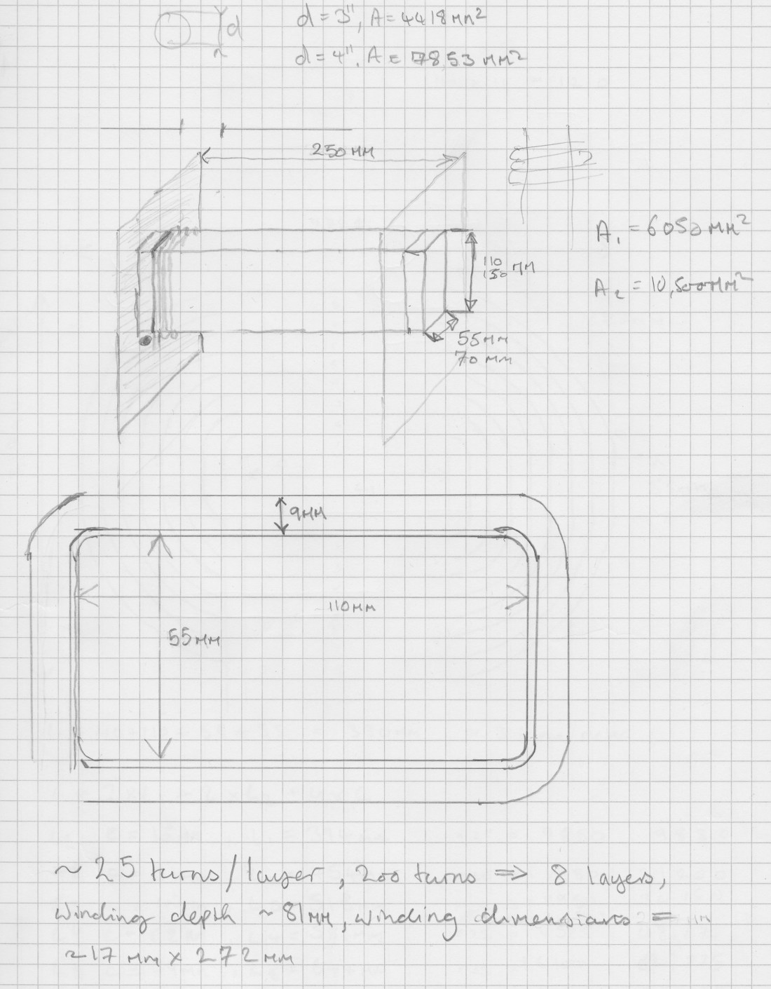
The first prototype to be built used the common 110mm x 54mm duct. The following sketches show the design for the coil form or bobbin.
One weekend I plied a friend with fruit cider and cigarettes, and we built the first winding engine:


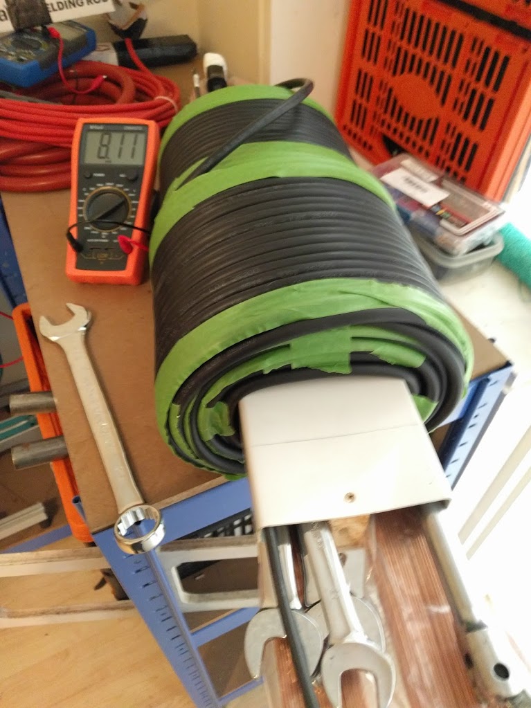
The coil was wound with 100M of 16mm² welding cable which is conservatively rated for 100A. It has the advantage that it is finely stranded and jacketed in a soft, flexible material, making it very easy to wind, but on the downside it takes up far more space than equivalent enamelled “magnet wire”.
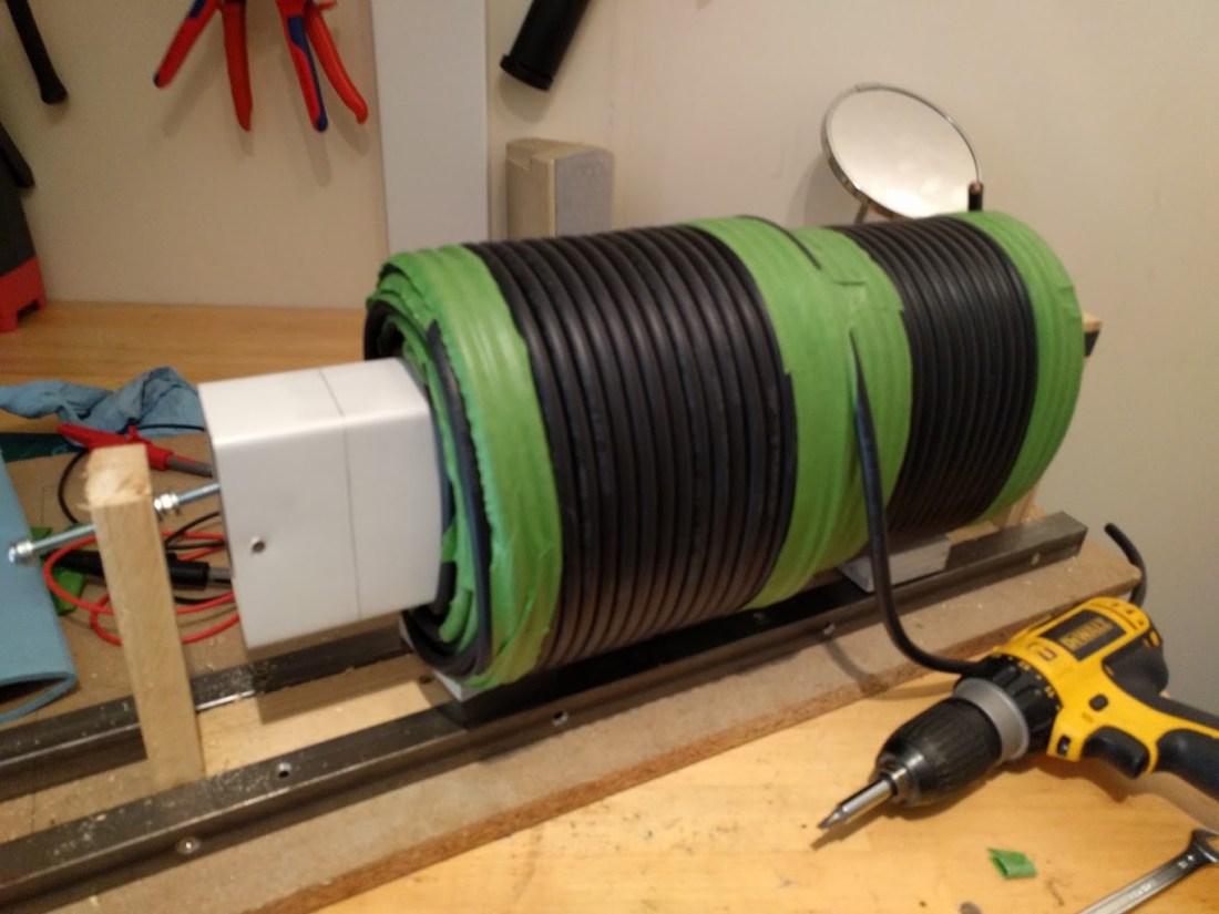
After surprisingly little time, all the available welding cable had been wound onto the form and secured in place and the curious assemblage of kitchen and automotive parts began to take on a more serious appearance.
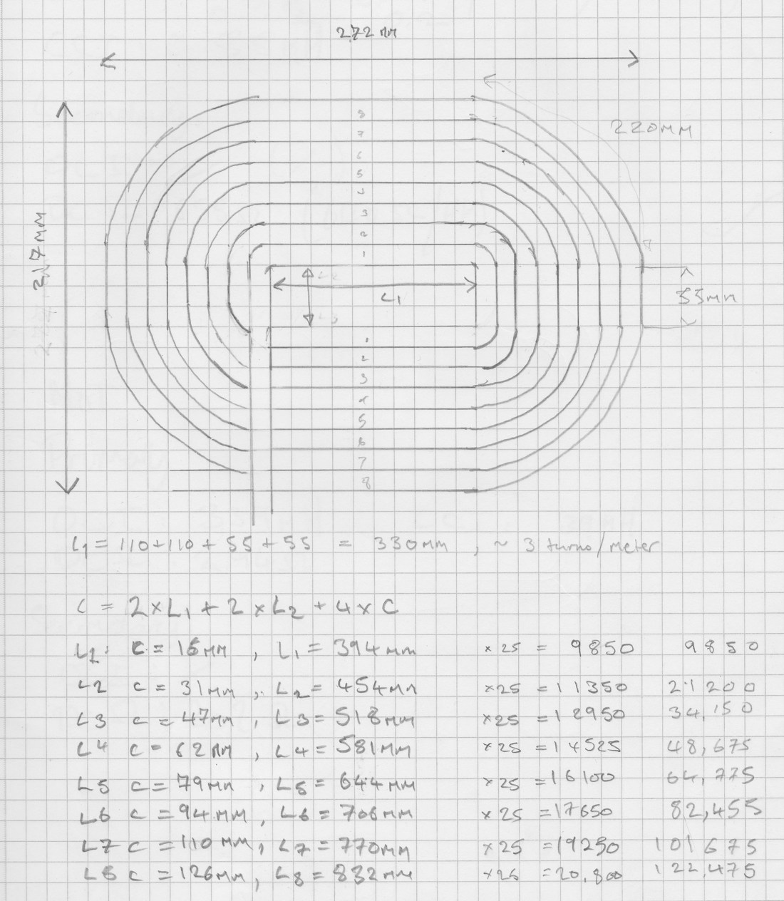
This coil has around 200 turns in six layers of 38 turns per layer (except for the last which is only a half layer). Length of the core within the winding is approximately 400mm and the core window CSA is 6050mm².
Core of the matter / matter of the core
Of course, the winding is only one half of the slide choke equation: to be able to use or test the device a magnetic core is required. In industrial fabrication, power transformer cores are almost always constructed from stacks of thin sheets of electrical steel (“laminations”) that are insulated from one another. This is done to minimise a type of loss that occurs when ferromagnetic materials are exposed to changing magnetic fields: the current flowing in the choke windings will induce currents in a solid iron object placed inside the field.
These are known as eddy currents and are a form of parasitic loss: energy is coupled out of the electrical circuit via the magnetic circuit, and then converted back into electrical current in the core material. These circular currents generate heat in the core and sap power from the electrical system. Failing to control eddy currents yields a choke that is inefficient and runs hot (in extreme cases it may actually melt parts of the core!).
After failing to find any second hand laminations with the right geometry for my build I decided to look to other sources. In the end I settled on 1000mm mild steel TIG welding rods. These provide a reasonable magnetic core, can be reasonably insulated from one another (to reduce eddy losses), and come in a form that makes adding or removing core material relatively easy.
The rods come in cardboard packets and are about 1.5mm in diameter. Initially I started packing rods into a jig and then cutting them to length with a grinding disc. In the end I began to just mark the cardboard packets with tape and cut them in place without the jig: the lengths don’t need to be particularly precise and it avoids fiddling around with hundreds of loose rods.


Testing the prototype
Once the first prototype was built it was time to find out whether or not it was up to the job. Back-of-an-envelope calculations suggested it might get close, but the proof of the pudding is in the wiring it up and poking it, if you ask me (monkey with a stick).
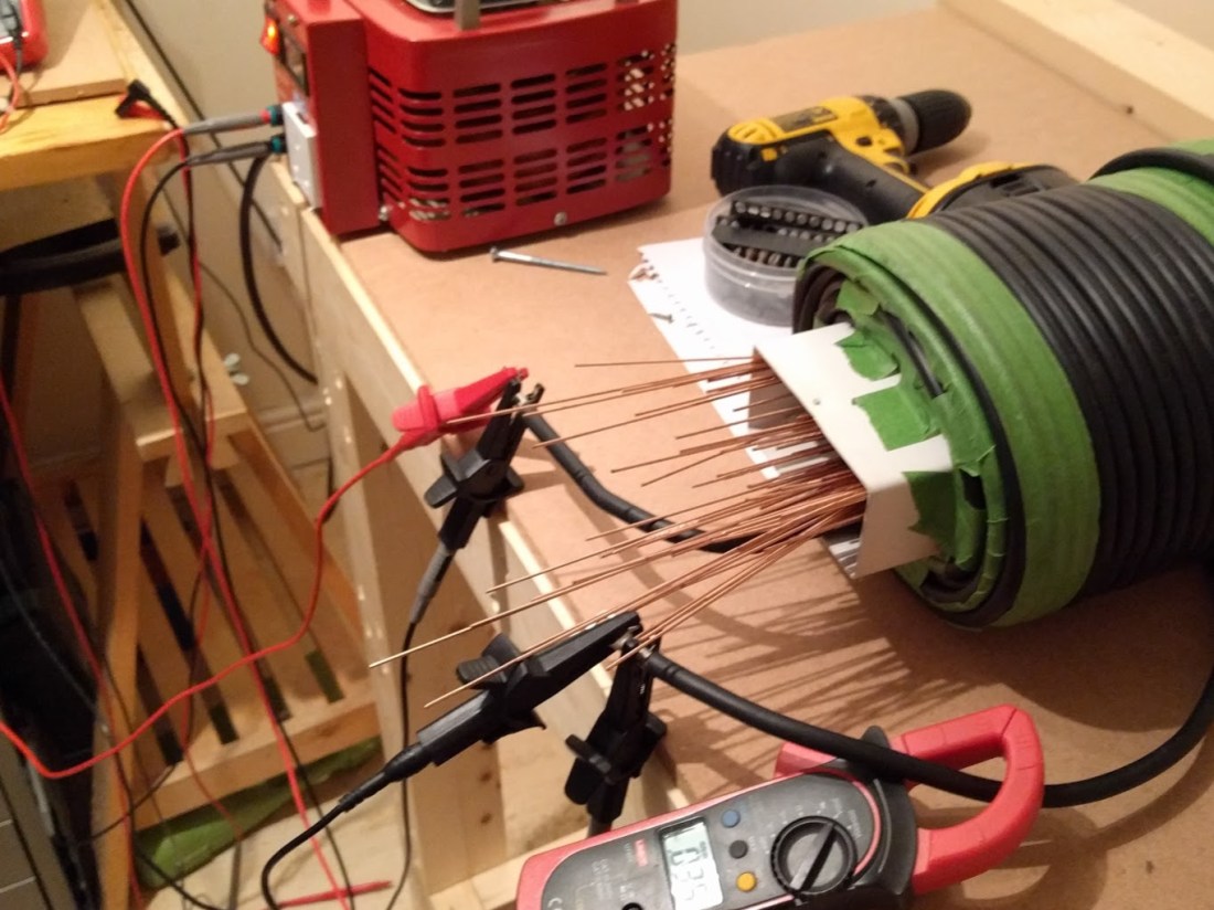
The first test is simply to attach an inductance meter to the finished winding, with or without core, and to determine if the measured inductance is in the acceptable range.
Here’s a picture of the first prototype, with as many welding rods as I could stuff into it, showing a measured inductance of 11.18mH:
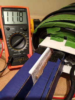
Taking the measured value and plugging it back into the equations we can determine the current that would flow through the circuit when fed from a mains supply:


Sixty eight point three three amps! And that’s on the low setting!
A touch high, perhaps… (Cue Doc: “What did I just say? ONE POINT TWENTY ONE JIGGAWATTS??!? GREAT SCOTT!”).
Even fairly desperate attempts to increase the core mass did not succeed in achieving an acceptable peak inductance.
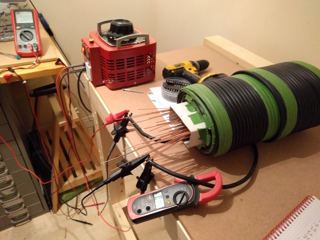
More advanced testing involves subjecting the ballast to higher voltage levels while monitoring the current flow in the windings. If the measured behaviour agrees with the predictions gained from the inductance measurement it’s a pretty good confirmation that the ballast will work as expected. During these tests the supply voltage, load, and degree of core insertion can each be varied independently.
The testing rig is pretty simple:
- 3KVA Variac (Chinese, with random fuse blowing feature)
- Multi-point current and voltage monitoring
- Optional dummy load (bombarding transformer with Jacob’s ladder)
Even though the inductance measurements indicated that the first prototype wasn’t going to quite cut it, I decided to get some more experience and measurements done before taking it apart.
CORE MASS EJECTION
Testing with the Variac was kinda fun, if a little scary at times. Everything held up admirably well: no smoke or bangs, although even at low power levels the rig throws off a heck of a 50Hz hum due to movement of the individual rods in the core.
At higher power levels, and with my first-cut homegrown hillbilly core things got even more exciting: above around 80V it began spitting out core rods. By 120V it was literally throwing them across the room: it was time to build Prototype #2.
I guess that’s probably enough inductive ramblings for another post: join me for part three where I’ll look at the final choke build, testing, and installation into the processing bench.
I’ll just share one more image for now: since I spent so much time talking about resistive ballasts, and then telling you why you shouldn’t use them, here’s one I made earlier. This is an 800W resistive in-line ballast. It’s great for heating my office, or generating indoor apricity on cold winter’s days.


Hi what about using an arc welder with magnetic shunt, connecter in series with a transformer? I’m actually about to get a pig pole transformer from US and assemble a bombarding station myself and considering that option.
LikeLiked by 1 person
Hey Lukasz, it’s a perfectly fine alternative using a very similar principle – the only real difference is that the welder is the variable shunt vs. the conventional slide choke with a core that can be withdrawn. It’s ultimately doing the same thing – adjusting the flux leakage to provide current limiting.
The only reason I didn’t go with that approach here was that I could not find a welder that was large enough, at the right price, and that would sit nicely in my (tiny!) workshop.
LikeLike